How to Make Water Move? Connecting a Circulation Pump to a Heating System
Installation of a circulation pump (CP) in the heating system of a private house is performed for more uniform and comfortable heating premises.
Installation may be required in the following cases: when the capacity of the pump built into the boiler is insufficient; when it is necessary to increase the circulation rate of the coolant in a gravity heating system.
CN to the existing system You can connect it yourself.
Content
Preparing to connect the circulation pump to the heating system
The process of connecting the circulation pump to the heating system consists of several stages.
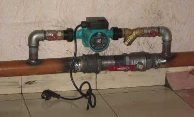
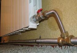
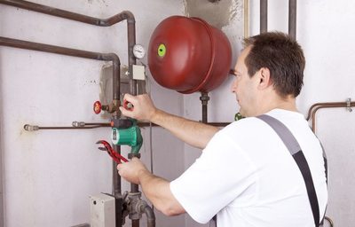
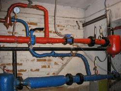
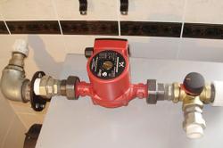
Photo 1. Circulation pump connected to the heating system. The device must be located in an accessible place.
Selecting a location
The installation location is selected based on the following considerations:
- Convenient access to the central heating system and its piping must be ensured.
- The device is placed after the expansion tank in the direction of the coolant flow.
- There should be no sources of leaks above the device.
Features of placement on the return line:
- the pump with piping is installed before the boiler shut-off valve;
- the passage of the coolant through the boiler is improved;
- the probability of cavitation is reduced due to the pressure of the water column from the system;
- It is necessary to install a mud collector in front of the pumping device.
Features of placement on the feed:
- the pumping device with piping is installed after the safety group and the boiler shut-off valve;
- The operating temperature of the device must correspond to the temperature of the coolant at the installation site.
Draining the coolant
Before installation It is necessary to drain the coolant from the system in the following sequence:
- Turn off the boiler.
- Connect one end of the hose to the system drain tap (the lowest one on the return line) or to a special tap on the boiler.
- Select a place where the coolant will flow out (into a special container, outside, into a sewer shaft). Place the other end of the hose in this place below the tap level, to which the first end of the hose is connected.
- Open the drain tap.
- Let air into the closed heating system (open the air vent at the highest point).
- Wait until the coolant has completely drained from the tap.
- Close the tap and disconnect the hose.
More about installation
Installation of the central heating system and its piping is performed in the following sequence (for a steel pipe):
- Before insertion The central heating system is pre-assembled separately with piping. depending on the selected connection scheme.
- The bypass is assembled separately. (branches to the existing boiler pipe, coupling with a coupling, a tap or a check valve). Packing of threaded connections is not performed at this stage.
- Assembled harness is fitted with branches to the bypass.
- On the bypass branches holes are marked for bends that are drilled with a crown.
- The bends are removed from the assembled unit. and are welded to the bypass bends. The bends are welded with the technological counter parts screwed onto the threads so that the threads do not warp during welding.
- Assembled units of the central pump and bypass disassemble and finally assemble with packing of threaded connections.
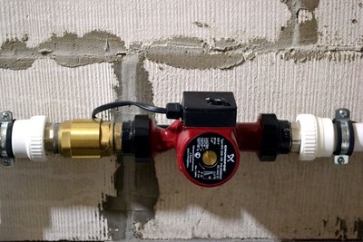
- Last but not least a pumping device is installed with union nut fastening through gaskets.
- Assembled unit of the central pump and bypass is fitted to the existing boiler pipe, markings are made, a piece of pipe is cut out, and the assembled unit is welded.
Important! When assembling and installing the harness, the rotor must always be located horizontally, and a group of terminals for electrical connection - on the top or on the side.
Supply of coolant
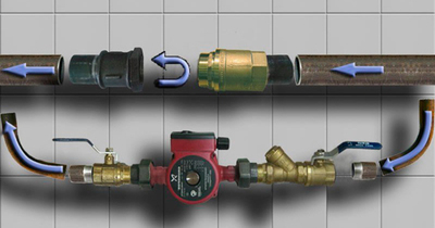
The central heating system is installed on the feed parallel to the feed pipe through shut-off ball valves and a mud trap. A union with a ball check valve is installed in the supply pipe, which is always mounted vertically (with the ball facing up).
Purpose of the ball valve:
- close the supply pipe when the central heating system is operating (the coolant flow goes through the pump);
- open the passage of the coolant through the supply pipe when the central heating pump is stopped (if it breaks down or the power supply is turned off).
Attention! It is prohibited to install a pump device and a check valve on the supply pipe. immediately after the boiler, before the safety group.

Return
The return circuit is similar to the supply circuit, except that the automatic ball valve is in the bypass. is replaced with a conventional manual ball valve.
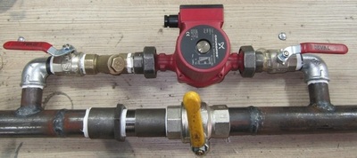
A ball valve is installed on the return pipe at the coupling, and parallel to the valve, branches with shut-off valves, a mud collector and the pump itself.
The mud collector is located before the pumping device (in the direction of the coolant flow), the mud collector spout should be directed downwards.
A bypass with a ball valve is needed so that when the device is replaced or breaks down, the circulation in the system, which is provided by the built-in pump in the boiler, does not stop.
For an open system
The piping of the central heating system installed in an open system must ensure natural circulation. when the device is disconnected or breaks down. The CN is installed on the return line through a bypass. In the bypass, either a ball valve (which must always be opened manually when the power is turned off) or a petal check valve (which opens natural circulation through itself automatically when the pump is not working) is mounted in parallel on the union.
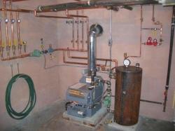
Connection to the boiler
When operating solid fuel boilers must not be allowed receipts in devices on the return line very cold coolant, because of this:
- inside the boiler chamber condensation is formed, which leads to pollution and reduced efficiency;
- the heat exchanger in the boiler may fail due to sudden temperature changes.
In order to protect the device from cold coolant, the boiler piping system additionally includes three-way mixing valve with thermal head. It is installed on the feed after the piping of the central heating system in the direction of the coolant flow. The second horizontal branch of the valve goes to the radiators, the lower branch goes to the feed. A thermal head with a temperature sensor is installed on the valve, which is fixed on the return pipe to the place where the lower branch is cut in from the valve.
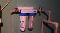
Filling with coolant
Before filling the system with coolant, the following is performed: rinsing with tap water:
- The system is filled with flushing water to pressure 2 bar.
- The tap is closed, the central heating system is turned on and the boiler is set to its lowest power.
- In 1 hour the condition of the mud collector is checked. If there is dirt on the mesh, it is removed from the mud collector and the system flushing continues for another within 0.5 h followed by checking the mud collector.
- The flushing is considered complete if there is no dirt in the mud collector.
- The flushing water is drained and the system is blown out with a compressor.
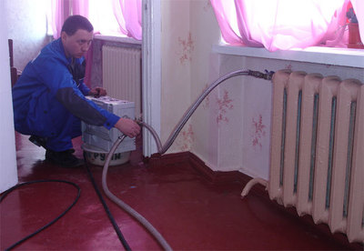
Filling the radiator system with the working coolant is performed using a pump (if the coolant is antifreeze):
- The system is filled with coolant up to pressure 2 bar.
- The device turns on.
- Excess air is released from the radiators, from the bottom floor to the top. In this case, the pressure in the system will drop.
- The coolant is pumped up to pressure 2 bar.
- The boiler is turned on to operating temperature.
System check
Examination is performed in the following sequence:
- Under verification tightness connections.
- Under verification uniformity of heating radiators, and if necessary, air is bled from them.
- If any radiator is completely cold, then all radiators except the cold one are closed, and the Mayevsky valve is opened on the cold radiator to fill it.
- The operation of the device is checked by ear. If extraneous sounds are heard, the pump and boiler stop for 20 minutes.
- After the foam has settled, the pump and boiler are turned on and the air is bled from the radiators.
Opening the central screw
Before each start of the central pump, air must be released from the device by turning the central screw. counterclockwiseIf this is not done, the circulation device will quickly wear out.
How to connect an additional pump. Scheme
An additional pump is installed in the heating system:
- when expanding heating system or installation of heated floors on each floor;
- if necessary, increase the circulation of the coolant at low temperature.
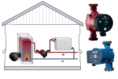
- Primary-secondary rings diagram
The main CN is included in the primary ring and produces circulation of the coolant from the boiler to the water intake points of the secondary rings and back.
Each secondary ring has its own central heating element., which circulates the coolant along its circuit. The length of the circuits and the power of the pumps are determined by calculations.
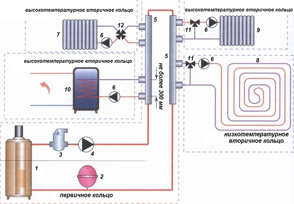
Photo 2. Installation of circulation pumps according to the secondary-primary ring scheme. Pumping devices are shown using black triangles.
- Scheme with hydraulic arrow
The hydraulic arrow is turned on between the primary ring and the collector, to which the central heating units are connected for each circuit.
How to properly connect to the power grid
The circulation pump must be connected to a differential circuit breaker and thermostat.
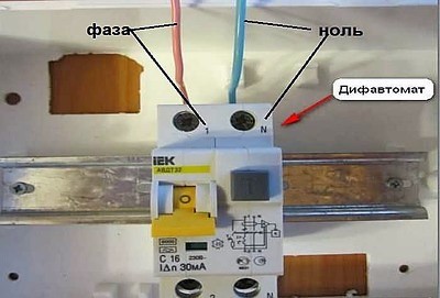
With differential circuit breaker
Connecting circulation equipment to a differential circuit breaker is performed in the following sequence:
- A three-core cable of the required length is cut and pulled through the corrugated pipe.
- The corrugated pipe with cable is laid from the panel in which the differential circuit breaker is installed to the pump, and is secured to the wall with clamps.
- The cable is fed into the terminal box of the central heating system and connected to the terminal. "L" phase wire (brown or white), to the terminal "N" neutral wire (blue or white and blue), to the terminal "PE" grounding wire (yellow-green).
- The opposite end of the cable is connected in the panel: the phase and neutral wires of the cable are connected to the corresponding terminals of the residual current circuit breaker, and the ground wire is connected to the ground terminal of the panel.
Connection to the thermostat
The thermostat is installed in the break of the phase wire:
- The neutral wire and the ground wire from the residual current circuit breaker are connected to the central heating circuit.
- The phase wire is connected to one terminal of the thermostat. The second terminal of the thermostat is connected with a suitable piece of wire to the phase terminal of the central heating system.
Features of connection in a private house
- During power outages, the coolant circulation must be performed when the central heating system is not working, which is implemented using a bypass.
- If a check valve is installed on the bypass, it must be periodically check for functionality, so that it doesn't stick due to salt deposits and dirt.
- It is advisable to connect the pump to a UPS rated for for 10-20 minutes (to prevent emergency situations).
Useful video
Watch the video, which tells where and how to properly install a circulation pump in a heating system.
Conclusion
Self-installation of the pump is not difficult if you have the skills of metalworking and welding. If you do not have the required skills or equipment, always You can contact qualified specialists.
Comments