Improving the efficiency of the system: the purpose of a heat accumulator for heating boilers
You are viewing the section Thermoregulator, located in the large section System components.
The heat accumulator significantly increases the service life of the entire heating system.
It also eliminates the possibility of cold liquid getting into the hot heat exchanger after the pump is turned on and the occurrence of cases of boiler overheating.
Content
Heat accumulator for heating boilers: what is it?
This element of the heating system is intended to retain excess heat and its return when necessary. It has a number of features.
Thermal accumulator device
The tank has a cylindrical shape and is made of stainless steel or black steel sheet. The capacity of the tank can vary in the range from 100 liters and reach up to several thousand.
Thermal units go as complete with insulation, supplied with them in separate packaging, and without it.
The width of the thermal insulation is 100 mm. This parameter is taken into account when installing the equipment. The insulation does not allow the liquid to cool down in the heat-accumulating tank for a long time.
The leatherette casing is placed over the insulated tank.
Design
The internal structure of the heat accumulator of the heating system can be simple and complex.
Simple view
In production direct connection and heat sources and consumption elements.
Heat accumulators with this design are used when:
- in the boiler and other elements of the heating system the same type of liquid is used;
- connection of heating circuits takes place using external heat exchangers;
- at an equal maximum pressure level in the boiler and coolant in the heating circuits;
- the temperature in the outlet pipe of the boiler is the same or slightly less temperature in the heating system elements.
Complex view
It is presented three different options.
Option 1
The essence of this design is that at the bottom of the battery container there is internal heat exchanger.
It represents spiral steel pipe made of corrugated or regular stainless steel. There are several of them.
The use of such heat accumulators is envisaged in the following situations:
- Parameters of pressure and temperature of the coolant in the heat source circuit exceeds the tolerance value for the consumption circuit.
- There was a need to connect several heat sources.
- Use of different heat carriers in heat source and heat consumption elements. This design of the heat accumulator provides for its mixing: heating occurs at the bottom of the container, and the less hot liquid rises to the top.
Option 2
Into a thermal device for heating built-in flow-through DHW circuit. The hot water intake point is located at the bottom. The cold water inlet is also there. The largest part of the heat exchanger is located at the very top of the heating device.
The use of such a design is relevant when the indicator hot water consumption is stable, uniform, without increased loads.
Option 3
The heat accumulator contains a tank for storing hot water for domestic purposes.
This design is used in situations where the maximum levels of heat energy generated by the boiler and hot water losses do not coincide.
Appearance
It is voluminous, roomy and tank insulated from the outside. It is connected to the heat source and heating system elements.

The principle of operation in the system
Heat carrier from the boiler moves through heat exchangers, placed inside the tank, partially saturating the liquid in it and in the additional compartment for hot water supply with heat.
When the fuel is completely burned, the coolant passing through the system cools down and liquid from the tank gets into it. Depending on the design of the heating system, the supply can be manual or automatic.
Installation
This process is ongoing taking into account certain nuances.
Installation Features
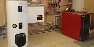
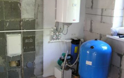
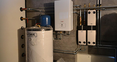
In a house with a small area it is acceptable to use standard scheme. The heat accumulator is mounted below or at the level of the boiler. In this case, the heat source is located below, so the heated layers will rise up. Therefore, There is no need to install a circulation pump.
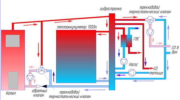
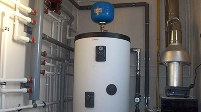
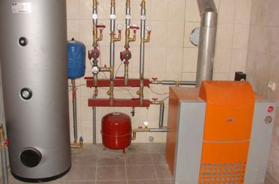
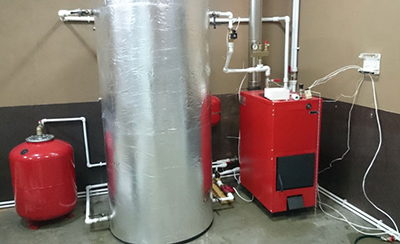
Photo 1. A typical installation diagram of a heat accumulator, which is located at the boiler level in the system.
The further the distance from the unit to the boiler, the greater the heat loss will be, since it will be necessary to lay a pipe between them. long section of pipeline.
To ensure that the device can be removed from the process at any time, it is positioned parallel to the pipeline with a built-in valve coming out of the boiler.
Formed on the incoming pipeline branch with valve to the heat accumulator. This makes it possible to switch the flow of the coolant from the boiler to the reservoir.
Important! Before you start to light the boiler, you need to do the following: reverse switching.
It is also necessary to take into account the following features of the installation of the heating unit:
- on all pipelines entering the heat accumulator mud filters are fixed;
- near the device is produced installation of a safety valve and pressure gauge;
- the room selected for installation of the heat accumulator must be well heated;
- thermometers are fixed on the inlet and outlet pipes;
- the connected elements are secured exclusively with flanges or threaded couplings;
- the site for the heating unit must be designed for a heavy load;
- there is an air vent on the upper outlet pipe;
Attention! You can't change anything on your own provided by the manufacturer design of the heat accumulator.
Sequence of actions
The process of installing the device is in progress in a certain order. Installation stages:
- Preparing the heating system, draining the coolant.
- Designation of the insertion area.
- Connecting branches to the pipeline, coming out of the boiler by welding.
- Installation of shut-off valves and thread cutting.
- Connecting the boiler bypass pipeline.
- Inclusion in the system heating the battery.
How to choose a heat accumulator for your home?
Exists a number of criteria, which are taken into account when choosing this device:
- Dimensions, weight. The capacity of the tank is determined in accordance with the boiler power. The larger the heat accumulator, the longer it will take to heat up, but the number of fireboxes will also be significantly reduced. If the dimensions of the device do not fit into the allocated room, then it is worth considering several tanks that have a smaller size.
- Power. It is calculated using the formula: Q=m*C*(T2–T1), Where m — mass of coolant, kg, WITH — specific heat capacity of the coolant, (T2–T1) — the difference between the final and initial temperatures.
- The material used to create the tank. Carbon steel with waterproof paint is used as standard. If possible, it is better to choose stainless steel equipment. It will be less susceptible to corrosion and impurities in the coolant.
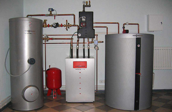
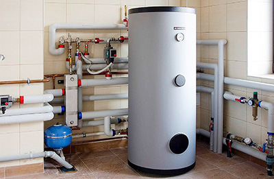
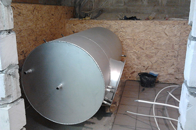
Photo 2. A large heat accumulator made of stainless steel is connected to the water supply system near the boiler.
- Availability of additional conditions. This is the installation of a built-in heat exchanger for connection to the hot water supply system, heating elements, auxiliary heat exchangers for connection to other sources of heating the coolant.
DIY Heat Accumulator
Most often used for this purpose finished cylindrical tank. The following materials are suitable for making the container:
- receivers from railway cars or industrial compressors;
- cylinders previously used to store propane;
- old iron boilers;
- Stainless steel tanks for storing liquid nitrogen.
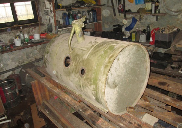
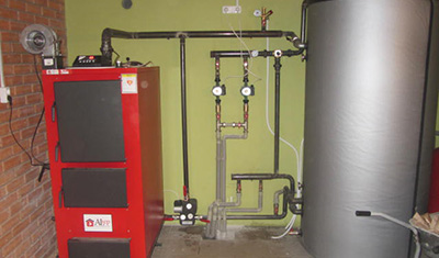
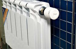
Photo 3. An old tank after storing propane is well suited for making a heat accumulator with your own hands.
Insulation
It is best to insulate a homemade heat accumulator basalt wool in rolls. Its thickness is about 7 cm, and the density is up to 60 kg/m3.
Attention! It is not worth using foam plastic and other polymeric materials.
To insulate the heating system device, you need to fill the tank with water. Thus, check for leaks. After that, do the following:
- clean the surface, cover it with primer and paint;
- wrap the tank with insulation, secure the last one with a cord;
- cut the facing metal, form holes for the pipes;
- fix the trim with screws to the fastenings.
Design calculation
It starts with determining the hourly and daily heat loss rate in the room. The resulting parameter will tell you how much fuel is needed for heating, and how much thermal energy will be released in this case.
Multiplying the hourly heat loss rate by the combustion time of one batch of fuel will determine the need to heat the building as a whole.
The difference between the amount of thermal energy released and the amount required to heat the house gives storage tank reserve indicator.
By dividing the obtained result by the hourly heat loss, you can calculate, How long will this energy last? This is how the number of required fuel loads is displayed.
After calculating these parameters, the time of full and partial loading of the system is determined, and the time of maximum charge of the heat accumulator is indicated. Based on the fact that how much energy is contained in 1 kW, you can determine its reserve by multiplying this value by the maximum charge of the device.
The temperature reserve is calculated by the difference between the maximum and required parameters. Knowing the heat capacity of the liquid, you can calculate required volume of the heating unit through the formula: energy reserve/(heat capacity of liquid*temperature difference).
Reference! When calculating the design, it is important to take into account all the features of the heating system and its exploitation.
Manufacturing stages
The formation of the thermal unit is carried out step by step:
- Preparing the container. If it was used previously, clean it from all dirt.
- Insulate the tank from the outside, securing the heat-insulating layer with tape wrapped several times.
- Manufacturing of a coil. A copper tube of length is suitable as the starting material. 9-15 m and a diameter of about 25 m. The pipe is formed into a spiral and built into the tank.
- Making pipes, equipped with taps. The latter will be needed to be able to shut off the water circulating in the system.
- Installation of heat accumulator. The tank is fixed to a previously prepared concrete platform.
- This type of device design is suitable for a single-boiler heating system. In a situation where there are several boilers, it will be difficult to manufacture the unit yourself.
Useful video
From the video you can learn about the function of the heat accumulator in the heating system.
Benefit
This device guarantees stability of the heating system with the conservation of electricity and physical strength, and the investment in it will pay for itself in the shortest possible time.
Comments