Here's what you need to know to calculate heating radiators by area in a private house
Knowing the exact data about heat loss allows you to design heating systems.
Even on the coldest day, with strong wind and high humidity, comfortable conditions will be provided, compliant with standards, in every room or other area of the house.
How to calculate the number of heating radiators for individual rooms of a private house
Based on the calculation results heat loss For each room, heat losses are determined, which should be compensated for by supplying heat using radiators.
Important! For such calculations, a building diagram is drawn up, as well as calculation table.
Building heat loss and dimensional characteristics
| Room number, premises | Dimensions of the room, premises, m | Room area, m2 | External wall area, m2 | Comfortable indoor temperature, °C | Notes | ||
| length (a) | width (b) | total length (a + b) | |||||
| 1 | |||||||
| 2 | |||||||
| … | … | … | … | … | … | … | … |
| n | |||||||
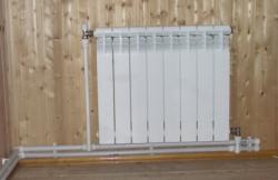
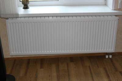
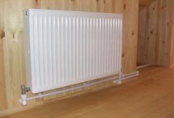
Radiators made of can be installed inside each room. cast iron, steel flat batteries, heaters baseboard type or aluminum radiators.
Bimetallic heating devices are usually not installed in private homes. Each type of batteries used has its own heat transfer characteristics.
Cast iron has a lower heat transfer coefficient than aluminum.
Heating pipelines can be steel, metal-plastic or polypropylene. Depending on the type of pipelines used, their heat transfer is taken into account differently.
Methods for calculating the number of batteries
In common practice, they use two different methods heat engineering calculation of the heating system. Most users prefer to use simplified method. It is quite simple.
Important! However, the error in the data obtained can sometimes reach values 15-20%. Therefore, competent designers always use a different method, it is called precise heat engineering calculation and selection of heating radiators.
The simplified method takes into account average heat output from the battery, without specifying the parameters of the coolant and the temperature inside the room. The data is adjusted later, after the installation of the entire heating system is completed, for which purpose adjustment ball valves are installed on the heating devices.
Installing taps in a certain position, achieve the required heat output. In this case, all performance checks and settings are performed long before the start of the heating season. In the future, the user is forced to independently adjust the operation of the devices depending on real conditions outside the house. Some people are lucky, then they achieve the necessary comfort in all rooms. More often, there are errors with the settings.
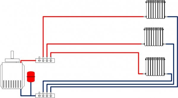
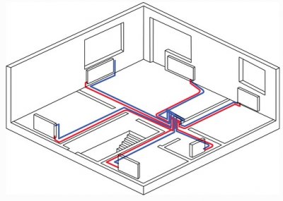
Photo 1. This is a schematic diagram of the radial flow of coolant to the heating devices.
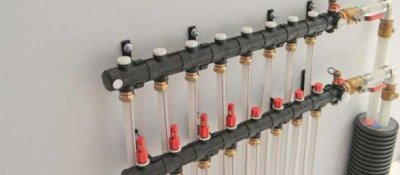
For a more reliable result, a different scheme for supplying the coolant to the heating devices has been proposed, it is called ray. Consists of:
- recharge boiler;
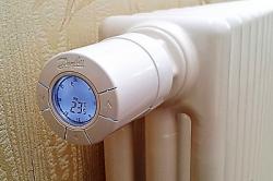
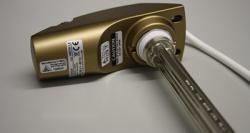
- air temperature sensor indoors, combined with a regulator;
- comb with automatic temperature controllers.
According to this scheme there is central coolant supply distributor. It is a comb on which several ball valves are installed, their number corresponds to the number of heated rooms. It is often used automatic maintenance scheme comfortable temperature, which is set on the thermometer in each room.
It is recommended in cases where the walls are long or when it is necessary to heat a significant number of rooms located on different floors.
Using a simplified method
The simplified method assumes that the temperature difference Δt = 70 °C. In fact, the value of Δt is not constant. It decreases due to the cooling of water in the pipes.
Reference! When using single pipe heating systems, the temperature pressure decreases constantly. Therefore, the accuracy decreases with increasing number of battery sections.
For each room, the number of sections is determined by the formula:
nsec=Fi/qsec , pcs, where:
- heat loss i-th room, W;
- heat transfer separate section of the radiator, W.
Heat transfer values for cast iron and aluminum appliances are presented in Table 2 and Table 3.
Based on the calculation results, the obtained data are entered into a table (Table 4).
Table 2. Heat transfer cast iron radiators
| Type of radiator | Section area, m2 | Maximum heat transfer at Δt = 70°C |
| M-140-AO | 0.299 | 175 |
| M-140-AO-300 | 0,170 | 108 |
| M-140 | 0.254 | 155 |
| RD-90 | 0.203 | 137 |
| RD-2n6 | 0.205 | 141 |
| B-85 | 0.175 | 112 |
Table 3. Heat transfer aluminum and bimetallic radiators
| Radiator type | Section area, m2 | Maximum heat transfer at Δt = 70°C |
| Aluminum A350 | 0.165 | 138 |
| Aluminum A500 | 0.254 | 185 |
| Aluminum S500 | 0.301 | 205 |
| Bimetallic L350 | 0.171 | 130 |
| Bimetallic L500 | 0.240 | 180 |
Table 4. Calculation of the number of batteries for heating a private house simplified methodology
| No. of premises, room | Heat loss of the room, W | Heat output of one section, W | Estimated value, pcs. | Actual value, pcs. | Note |
| 1 | |||||
| 2 | |||||
| … | … | … | … | … | |
| n |
The actual value is taken into account rounding up. If there are any special conditions for installing batteries, they are specified in the “Note” column.
According to the refined methodology
The updated methodology takes into account the features of the heating system, the installation of heating devices in the premises, as well as the organization coolant supply to each battery.
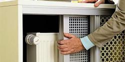
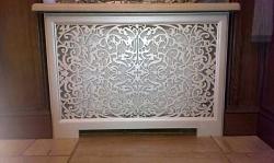
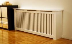
Attention! The desire to hide radiators from outside view leads to a decrease the efficiency of their use. This, in turn, forces the installation of additional sections.
When performing calculations, a simple formula is used that determines the surface area of heating devices in a separate room:
Fat= ((Fi - Fthree)β1 β2)/(kpr (tat - tvi)), m2, Where:
- heat flow, received from supply pipelines, W;
- coefficient, taking into account the peculiarities of installing the radiator in the room;
- coefficient, which determines the characteristics of the heat flow from the supply pipelines. For single-pipe open laying systems, with two-pipe installation;
- coefficient Heat transfer of radiator, W/(m2·°С);
- average coolant temperature in the radiator, °C;
- meaning comfortable temperature in a given room of the house, °C.
The heat supply from the supply pipelines in the room is calculated as:
Fthree= kthree Fthree (tthree - tV) ηi, Tue, Where:
- coefficient heat transfer from the pipe into the room, W/(m2·°С);
- square supply pipes, m2.
Fthree = πdl, Where:
- diameter pipes, m;
- length eyeliner, m;
- temperature pipe surface, °C;
- coefficient, depending on the position of the pipe in space, horizontal connections = 1.0, vertical connections = 0.75.
The values of the coefficients characterizing the method of installing batteries are shown in the table.
A coefficient that takes into account the specific features of the radiator installation, β1
| Method of installing batteries | The value of the coefficient β1 |
| Free installation | 1.0 |
| There is a window sill | 1.05 |
| Installation in a niche, A = 40-10 mm | 1.11 |
| Cabinet installation, A = 150 mm | 1.25 |
All calculations using the exact method are summarized in a table (Table 4).
By area
The main calculations are carried out based on the area of the premises. In this case, the following are taken into account: equal height walls in all rooms. In reality, there may be certain differences. If they exceed 5%, then a recalculation is necessary.
By volume
For non-standard rooms, such as double-height rooms, clarification is required. SNiP there is a simple recommendation, multiply each cubic meter of area is 41 W.
So, for the room (width x length x height = 3.5 x 6.0 x 5.2 m) the volume will be 109.2 m3Taking into account the requirements of SNiP, to heat this volume you will need:
109.2 x 41 = 4,477.2 W = 4.48 kW.
Useful video
Watch the video to learn how to calculate the number of heating batteries.
Important nuances
Results:
- To select radiators for a private house I uset two basic methods of simplified and precise calculations.
- The first method allows you to quickly estimate the required number of sections for heating devices. But the error can be more than 15-20%. Therefore, all results are rounded up.
- The second method gives a more accurate result. Error does not exceed 5%. That is why designers use this method when developing a residential building project.
- Special clarification on heating large volumes in rooms with second light are produced by calculating the losses for heating a given space according to the requirements of SNiP. In this case, heat losses through enclosures are not taken into account, since the value of volumetric heat consumption is higher.