They will maintain the stability of any system! Heating valves: what are they?
Valves (valves) for heating are installed at the nodal points of the heating system to ensure that the coolant parameters correspond to the calculated values.
Valves are elements of shut-off and control valves.
They are installed on a pipeline or radiator to change or stabilize the parameters of the coolant – direction of circulation, flow rate, pressure.
Content
Heating valves: what should be taken into account when choosing?
According to their functional purpose They are divided into the following types:
- safety;
- air vents;
- reverse;
- balancing;
- bypass;
- three-way.
Calculation when designing a heating system is performed in the following sequence:
- The parameters of the coolant at nodal points are calculated - temperature, pressure drop, flow rate.
- Based on the obtained values, the type and rating of the valves are selected.
- Preliminary settings of the adjustment elements (positions of the adjustment handles) are calculated.
When selecting the type and denomination, the following criteria are taken into account.
Type of coolant
The coolant can be either water or antifreeze - ethylene glycol, propylene glycol and others.
Features to consider:
- By the water on 15-20% greater heat capacity than antifreeze.
- Antifreeze reacts with zinc, so valve assemblies should not be zinc coated.
- Maximum temperature of coolant with antifreeze — not higher than 75ºС (at higher temperatures, vaporization begins). This is taken into account when setting the safety group valves.
Temperature conditions
When designing a heating system, it is established maximum and minimum temperature of the coolantAccordingly, all heating valves must function normally within the specified temperature range.
Important! When calculating the parameters, it is necessary to include in the project not formal (standard) initial data on the temperature regime, but real ones. For example, the temperature of the carrier received from city networks may not be 150ºС, as in the technical conditions, and 110—120ºС. The coolant consumption will be different in both cases. 2 times.
Pressure in the system
All valves must be resistant to maximum pressure in the heating system, which is calculated during design.
The calculation and selection of safety, bypass and balancing devices depends on the pressure values.
Section
From the flow section depends on the throughput — the amount of coolant passing through the valve per unit of time.
When choosing a valve with a smaller value flow section, there will be a violation of the circulation of the coolant. Selection with the highest calculated value will lead to an unjustified increase in the cost of the system.
Characteristics of different types of valves
Valves for heating systems differ according to its purposeThey come in the following types.
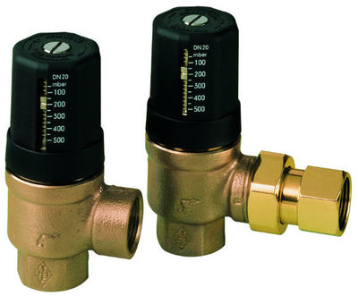
Safety
The safety device is installed in order to protect the heating system from damage, caused by water hammer or pressure increase above the calculated value.
In apartment buildings, safety valves are installed on the return pipe and are designed for maximum pressure. 6 bar.
In private houses they are installed on the supply pipe next to the boiler (in the safety group) at maximum pressure. 3 bar.
Design features
The device looks like this in the form of a metal tee, along the horizontal section of which the coolant circulates. The vertical branch is closed by a spring-loaded membrane. The spring elasticity value is calculated for the maximum permissible pressure value in the system.
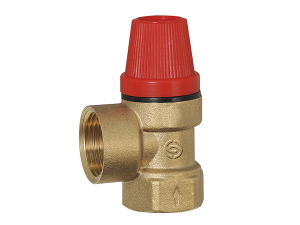
Photo 1. Safety valve for heating systems. Made in the form of a tee, in the upper part there is an adjustment handle.

Operating principle
At normal pressure, the membrane is tightly pressed against the inner seat of the device and does not allow the coolant to pass into the vertical section. When the pressure increases above the estimated the membrane opens, the flow of coolant rushes into the vertical section of the device and is discharged outside.
By removing excess coolant outside the circuit the pressure in the system is normalized and the valve closes.
Attention! Safety valve cannot be connected directly to the sewer for draining the coolant. It is recommended to install a container under the structure where the coolant will be drained, as an indicator of the device's operation.
Air vent
The air bleed valve is designed to remove accumulated air or gases from the system, which impede normal circulation of the coolant and cause corrosion of metal parts.
Design features
Air vents are divided into two groups:
- Automatic valves are installed at the highest point of a closed system (in open systems, the expansion tank acts as an air vent).
- Manual devices (Maevsky taps) are installed in the upper opening of the radiators.
Auto The valve is a metal barrel with a threaded branch pipe. At the top of the barrel there is a nipple for bleeding air. Inside the device there is a cavity with a float, which is connected by a rocker to the locking element of the nipple.
Manual An air vent is a radiator cap with a screw. The screw closes the hole in the cap to release air.
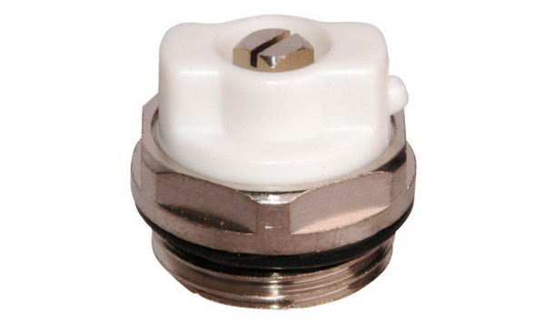
Photo 2. Manual air vent for heating systems, otherwise called "Maevsky crane".
Operating principle
In automatic The valve allows air to enter the device and accumulate in the cavity above the float. As air accumulates, the float begins to descend, the rocker opens the locking element of the fitting and the air comes out. After the air is released, the float rises and the fitting closes.
To bleed air using a hand valve, which has accumulated in the battery, the screw is turned with a screwdriver or a special key. The hole in the plug opens slightly, air comes out of the radiator. After a stream of coolant appears from the hole, the screw is closed.
Rules of use:
- Automatic air vent must be installed vertically onto the pipeline with the nipple facing upwards. The protective cap is removed from the nipple.
- It is necessary to bleed air from aluminum radiators at least once a month due to the possibility of electrochemical reactions with the coolant.
Reverse devices
The check valve is installed in sections of the heating system circuits where it is required movement of the coolant in one direction only.
These areas are:
- Bypasses, shunt circulation pumps.
- Feeder nodes tap water systems.
- Schemes with simultaneous connection several boilers for hydraulic isolation.
Design features
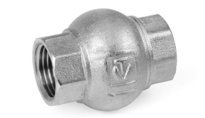
Check valve consists of a metal body with threaded connections, in which the locking mechanism is located.
According to the design of the locking mechanism, reverse devices are divided into the following types:
- Spring or disc. The locking mechanism is a plate pressed against the seat by a spring.
- Differential or ball. The locking element is a light ball made of heat-resistant rubber, which, under the action of its own weight, closes the funnel with an opening for the passage of the coolant.
- Petal or gravity. A locking element-petal, fixed to the upper point and pressed against the seat seal under the action of its own weight.
Installation rules:
- The return device is installed in the direction of the coolant flow - from the inlet to the outlet (along the arrow on the body).
- The ball device is installed vertically, with the ball facing up.
- The petal apparatus is installed horizontally.
Operating principle
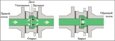
The locking mechanism of the device opens to allow the coolant to pass in a straight direction, if there is a certain pressure difference — the difference between the pressure at the inlet and outlet.
Spring loaded valves have the highest minimum pressure drop (from 0.025 bar) to open the mechanism. Therefore, they are not recommended to be installed in gravity systems.
Petal and ball open at any positive pressure difference.
Balancing device
Balancing devices are designed for balancing heating circuits or radiators according to the thermal regime, with the aim of uniform heat distribution. The purpose of balancing is to ensure the calculated value of coolant flow for each radiator or circuit.
Depending on the installation location The following types are distinguished balancing valves:
- Main lines valves - on return pipelines of long heating circuits (in multi-story buildings).
- Radiator valves - at the outlets of radiators connected to one circuit in a one-pipe system.
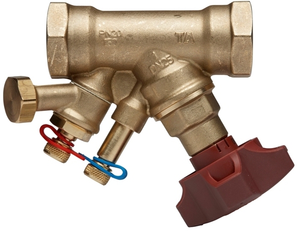
Photo 3. Balancing valve for heating systems. The adjustment handle is located at the bottom.
Design features
Balancing valve consists of a metal body with threaded connections for connection to pipes. The adjustment handle on the valve determines the degree of blocking of the passage opening by the conical valve.
The body may be marked scale for fine adjustment flow rate of the coolant passing through the passage opening. The main valves have nipples for connecting pressure gauges.
An important characteristic of a balancing valve is Kvs or maximum throughput. It determines the flow rate of liquid (m³/h), passed through a fully open valve with a pressure difference at the inlet and outlet of the valve 1 bar.
Important! The balancing valve should be selected not according to the diameter of the pipes, but under the calculated Kvs value.

Operating principle
Each balancing valve in the system is adjustable for a certain value of the flow cross-section to regulate the flow rate of the coolant. Balancing is performed either according to calculations made at the design stage or empirically. If the pressure drop value is unknown, the pressure is measured before and after the valve (the device is connected to the measuring nipples on the main valve). According to the obtained values and the valve adjustment diagram the position of the adjustment handle is determined.
Bypass valve
Bypass valve designed to stabilize pressure differences (the difference between the pressure in the supply pipe and the pressure in the return pipe) within the calculated values.
This is necessary for normal circulation of the coolant through the circuit.
Unlike the safety valve, which discharges excess coolant beyond the limits systems, the bypass directs this excess from the supply directly to the return so that the pressure difference does not exceed the specified value (optimal - 1.2-2.5 bar).
Design features
Bypass device consists of a metal body with two threaded pipes and an adjustment handle, which sets the device response threshold. The valve is connected with its input to the feed pipe, the bypass outlet for excess coolant is connected to the return line.
The adjustment handle sets the degree of compression of the spring, which presses the gasket against the seat of the bypass outlet, blocking it or opening it for the passage of the coolant, depending on the pressure difference.
Operating principle
In normal position The bypass outlet of the device is closed.
If the pressure difference becomes greater than the calculated one (for example, when all thermostatic valves on the radiators in the circuit are closed), then under the influence of this difference the spring is compressed and opens the passage for the coolant from the feed to the return, bypassing the heating circuit. To prevent this flow from going into the circuit, a check device is installed on the return.
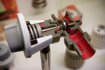
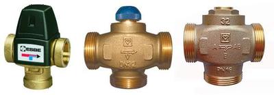
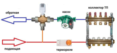
Three-way device
Three-way thermostatic mixing valves are divided into two groups:
- Distribution divides the input stream coolant in two directions.
- Mixing mixes two streams into one output stream.
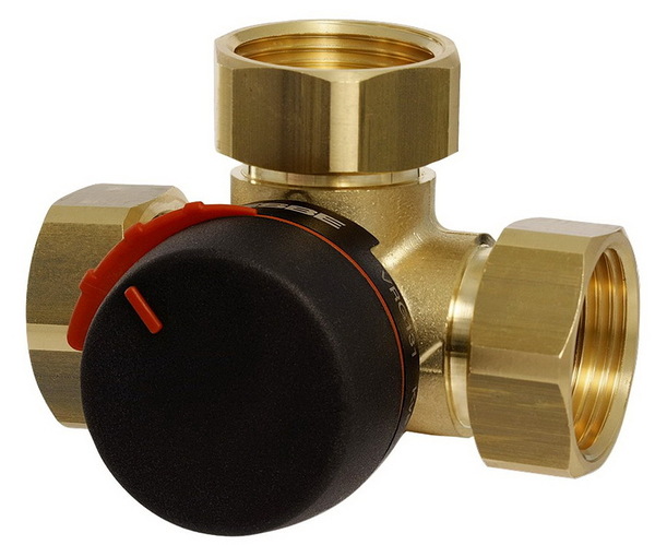
Photo 4. Three-way valve for heating systems. Made in the form of a tee, there is a handle for adjusting the operation.
They are applied three-way devices in the following diagrams:
- protection of boilers from low temperatures of the coolant in the return line;
- temperature regulation in underfloor heating circuits.
Design features
Frame three way valve has three branches:
- at the distribution - one input and two outputs;
- at the mixer - two inputs and one output.
There are three chambers inside the case., which are closed by two valves located on one stem. The stem moves under the action of the thermal head, simultaneously closing both mixing inlets (for the mixing valve) or both mixing outlets (for the distribution valve) in a certain proportion.
The degree of distribution or mixing of flows depends on the temperature of the sensor, associated with the thermostatic valve head.
Operating principle
When the distribution device is operating in the boiler protection circuit against low return temperature, it is set to feed, The valve inlet faces the pump.
One way out (horizontal) is connected to the heating circuit, second The output (bypass) is connected to the return line. The temperature sensor is installed on the return pipe between the connection point of the vertical outlet of the valve and the heating circuit.
At low return temperature after the circuit, the valve outlet to the heating circuit is closed, the outlet to the return line is fully open. The heated coolant after the pump returns back to the boiler.
As the return line heats up, exiting after the circuit, the vertical outlet of the valve gradually closes, redirecting an ever-increasing flow of coolant into the circuit. After the return line has finally warmed up, the entire flow goes through the circuit, the bypass outlet of the valve is closed.
Useful video
Watch the video to learn how to properly install a three-way valve in a heating system.
How not to go down the drain
Heating valves play an important role in ensuring operability systems.
Their selection, installation and adjustment must be carried out only after precise calculation of all parameters. Otherwise, you may end up with poor heating of the premises or an overrun in the estimate when valves with excessive functional redundancy are included in the project “just in case”.

Comments