Guarantees balance in the system and protection from harmful impurities! Do-it-yourself hydraulic arrow for heating
You are viewing the section Hydraulic arrow, located in the large section System components.
The hydraulic arrow is a plastic or metal structure, balancing the temperature difference between the boiler circuits and consumers (radiators, underfloor heating systems, indirect water heating).
Serves as a settling tank for heavy impurities and air, allows to achieve the calculated liquid supply.
Content
Types of hydraulic arrows for heating
Separators are classified according to a number of parameters:
- Form - round, square.
- Number of contours - four, six or eight inputs/outputs.
- Placement of tubes — along one axis/alternating.
- Installation — vertical or horizontal. The first option removes sludge and excess air from the coolant. The second scheme is used if there are additional filters.
Purpose
Hydro separator - additional unit that maintains the integrity of the heat exchanger from water hammer. The procedures of initial start-up, technical inspection, and boiler maintenance are accompanied by the shutdown of the circulation pump, which contributes to the formation of air locks.
Arrangement of a hydraulic separator — mandatory requirement when installing cast iron heat exchangers, since the temperature difference between the liquid at the outlet and inlet destroys the metal. The hydraulic arrow equalizes the pressure when the flow rate in the main circuit and the total indicators of the consumer pipes do not match.
Cleaning the coolant from rust and scale, extends the service life of moving and rubbing elements main line. For example, pumping equipment, shut-off valves, meters, temperature sensors. Prevents damage to the heating main line during automatic blocking of the hot water supply, "warm floor" system.
Operating principle
When the system is first started, cold liquid, driven by the pump, circulates in the pipes and enters the hydraulic arrow.
The hot coolant rises upward, the cold coolant descends downward to the boiler for further heating. mixes cold and hot liquid streams naturally, collecting excess air and harmful deposits.
How to do it yourself: preparing tools and materials
Self-assembly of a hydraulic arrow requires the use of:
- welding machine;
- hammer;
- grinders;
- collector (a profile pipe is enough 80x80 with a wall 3 mm);
- two square washers to the ends;
- two threaded elements for air release and drain cock;
- two boiler pipes with thread diameter 25 mm;
- 6 threaded parts of 20 mm for consumers (2 for heating, 2 for underfloor heating, 2 for indirect heating);
- pressure gauge;
- cranes;
- bimetallic crowns 25 and 29 diameter, drills 8.5 mm;
- welding electrodes (3 mm);
- primers, hammer paints.
Attention! Necessarily check the quality of the connecting parts with a levelInstalling crooked threads will damage taps and pumps.
Preliminary calculations
To create drawings of hydraulic arrows It is necessary to correctly determine the pipe diameter.
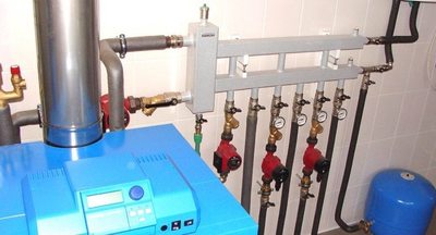
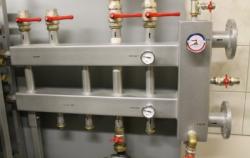
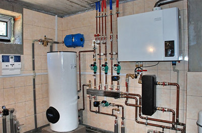
Photo 1. Metal hydraulic arrow installed in the heating system. Before installation, it is necessary to calculate the diameter of the pipes.
Calculations are carried out according to the formula: D=49*√W: Δt, Where:
W — capacity of boiler equipment.
Δt — temperature difference.
The length of the collector should correspond to six diameters, and the distance between the tubes should be equal to 2-3 ØUsing the obtained data, they draw up assembly diagrams of the device.
Manufacturing sequence, diagram
In a pre-prepared collector, holes are burned with an electrode according to the markings. For 3 consumers use a profile pipe of length 900 mm. A chamfer is made on the end surface of the couplings approximately 1 mm. Mark the location of the collector pipes: on one side 3 feeds, 3 returns. They are retreating 50 mm from the edge of the "cold" and "hot" sides, they are taken away 150 mm each for 3 branch pipe inlets.
On the opposite wall of the pipe, a hole is drilled for the supply circuit (opposite the middle branch for consumers). From this hole, measure 250 mm, drill an additional gap for the return. The resulting design provides for the placement 6 pipe inputs consumers on the one hand, 2 holes for boiler contours from the opposite.
A step drill will be used to create the initial holes. Reach the required diameter for the thread entry ¾ a crown will help 20 mm. Additional nozzle (diameter 29 mm) create inch holes for the boiler circuit.
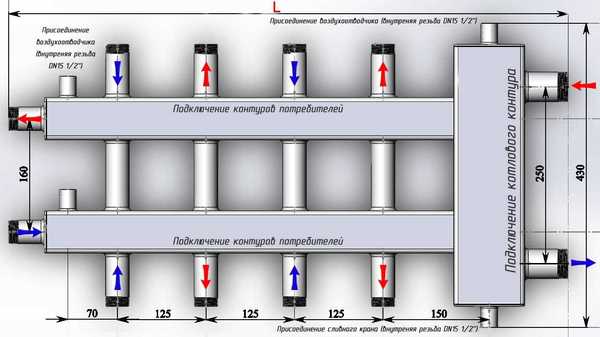
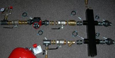
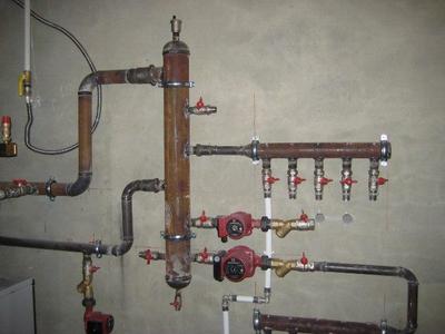
Photo 2. Hydraulic arrow diagram for the heating system. The pipes to which the hot water circuit is connected are shown in red, and those with cold water are shown in blue.
Square washers act as plugs. Steel couplings are welded to the plates. The ends are cleaned, the edges are beveled, and tacked to the separator with a welding machine. The first seam is formed, cleaned, and additional cladding is carried out by welding.
The thread for the boiler circuit and consumer pipes is welded onto the cleaned hydraulic arrow. Having screwed on the cast iron plugs, the device is prepared for testing. The pumping equipment that drives the water is connected. The working pressure is monitored (2 atmospheres) through the drain cock nipple. It remains to prepare the hydraulic arrow for painting, having previously protected the threads from the finishing material.
The device is installed vertically, horizontally, or at an angle. The air valve is placed at the top, the drain valve at the bottom.. Complex structures are equipped with horizontal partitions. The sludge collector and magnetic catcher are placed at the bottom of the body. Aeration occurs at the top.
Advice. Professional craftsmen recommend equipping hydraulic arrows pressure gauges, providing pressure control in the heating network.
Boiler piping
The hydraulic distributor is connected to the boiler through the supply and return pipes.
Hot water rises through the upper tube and is divided between the consumer circuits. The cooled liquid flows back to the lower tube of the hydraulic distributor.
Using a combless system, the number of taps into the hydraulic arrow will increase. The pipe connecting the first boiler circuit with the separator is distributed by height.
Fulfilment of this condition helps to improve the quality of liquid collection by secondary branches.
Collector functions
The collector is installed in a network that uses more than 3 radiators. The pipes for draining water to consumers are connected to the comb. The falling pipes are on top, the return pipes are at the bottom. Hot water from the boiler moves through the upper branch pipe, cold water through the lower circuit. The heat exchanger is located on the side, on the back side of the hydraulic arrow. The diagram provides for presence of balancing valves between the supply/return manifold. The control valve increases the flow rate and pressure on the circuits farthest from the separator.
Installation of shut-off valves
By accepting a fast flow of coolant, the hydraulic arrow slows down the movement of water. The air released into the liquid accumulates at the top, where it is installed. air vent.
The device's shut-off valve allows for the replacement of automation in an emergency, maintaining the working condition of the heating network.
An alternative to automatic air vents will be Mayevsky crane, requiring periodic unscrewing to remove mechanical deposits.
DIY installation of a polypropylene hydraulic arrow
Having decided to create a polypropylene divider yourself, it is enough to prepare a hollow pipe of circular cross-section equipped with nozzles for connecting the heating network. The feed circuits are usually located at the top, the return circuits at the bottom. The tees are connected to each other with pipe sections, the ends are closed with plugs. The work is carried out using a welding machine with attachments.
By connecting a wall-mounted boiler to the maximum with a capacity of 40 kW, it is preferable to use a ring collector for 2-4 circuits. The manifold and the hydraulic arrow operate in one housing, devoid of internal partitions. The heat carrier constantly circulates through the boiler and manifold. Heat is taken from the plastic comb by a pump group. The simplified design of the PVC buffer will take up a minimum of space and costs.
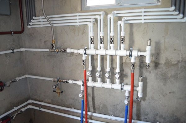
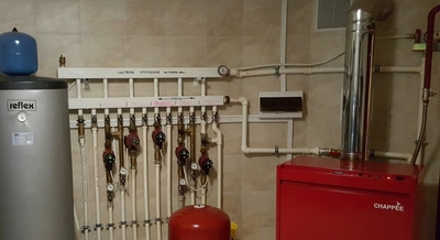
Photo 3. Polypropylene hydraulic arrow. The hot coolant circuit is connected to the upper part of the structure, and the cold one to the lower part.
Pros and cons of polypropylene products
Polypropylene dividers will provide Main advantages systems:
- Smooth surface of the material will reduce the resistance of the coolant, reducing the boiler's heat losses.
- Polypropylene convenient to paint outside with heat-resistant paint.
- The cost of the plastic structure is cheaper analogues.
- Plastic products prevent the formation of corrosion.
- Work effectively with boilers with a capacity of up to 35 kW.
- Correct pressure in the system.
- Automatically distribute thermal flows in the required direction.
- Smooth out water hammer.
- Increases boiler efficiency, fuel economy.
Flaws polypropylene dividers:
- Unable to install hydraulic arrows in a system with a solid fuel boilerPolypropylene is subject to rapid wear under high pressure and temperature.
- Installation of the structure uses additional equipment (welding machine for polypropylene), couplings, bends, taps.
- Diameter of the hydraulic arrow must correspond to three circles of the pipes contours (60-90, 120 mm). Pipes of the required dimensions are rare and expensive.
Important! Solid fuel boilers often heat water up to 90-95 °CPolypropylene can withstand temperature loads, but in an emergency (power outage) the coolant in the feed heats up up to 130 °C.
Useful video
Watch the video, which talks about the design and operating principles of the hydraulic arrow.
Recommendations from experts
Hydraulic separators are often equipped with pressure gauges and temperature sensors, necessary for complex heating systems. When planning heating with one or two radiators, many craftsmen neglect the installation of automatics.