What is a heating system impossible without? Technique, calculation and installation instructions for different types of heating pipes
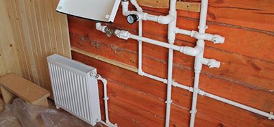
They are used for heating different types pipes.
Material, type and flow area are selected depending on the operating conditions of the heating system: coolant temperature, operating pressure, installation method.
Content
Installation of metal systems
Before installing a heating system made of metal pipes the project is being developed (drawing) which specifies:
- length and cross-section of workpieces;
- location of fittings, shut-off and control valves, heating devices;
- length and dimensions of the threads cut on the workpieces;
- welding joints;
- radii for execution of corner elements;
- locations of brackets for fastening pipes.
Preparatory work is carried out on the workbench before the final installation of the system:
- cut the blanks to size;
- cut a thread;
- assemble individual sections on threads;
- bend corner elements using a pipe bender;
- weld pipes into a rotary joint.
Gas welding
The weld is being formed from molten metal in a torch of burning gas (a mixture of acetylene and oxygen).
Pros gas welding:
- easy correction of welding defects;
- hard-to-reach areas can be easily welded;
- does not require electricity;
- can be done over rust and paint.
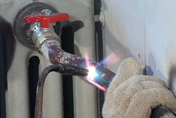
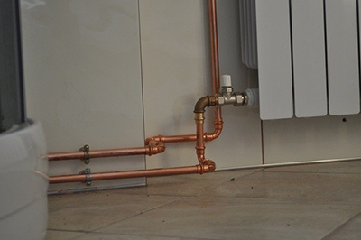
Photo 1. Installation of metal heating pipes using gas welding is easy to carry out even in hard-to-reach areas.
Cons gas welding:
- bulkiness and explosiveness of the equipment;
- not used for diameters greater than 50 mm;
- When burned, the weld becomes brittle.
Solder
Solder is used for soldering copper pipes into fittings. Soft solder is mainly used. Rothenberger solder wire No. 3. It has a melting point 230–250 ºC, can be done with a propane torch. Flux is used to remove oxides from copper and improve solder flow.
Reference! Soldered joints have high strength and tightness. Penetration of solder into the gap between copper parts occurs due to the capillary effect.
Soldering technology:
- Cut the workpiece evenly Use a special knife to remove burrs.
- Clean it with sandpaper until it has a metallic shine on the outside (to the length of the entry into the fitting), and with a brush – the fitting on the inside.
- Apply flux paste (marked with the number “3”) on the outer surface of the workpiece and the inner part of the fitting.
- Bend a 3mm diameter solder rod for a length equal to the outer diameter of the workpiece (solder consumption for one joint).
- Connect the parts.
- Heat the joint with a propane or acetylene torch to the melting temperature of the solder.
- Introduce solder to the soldering point. Its rod should melt to the marked length and be drawn into the gap between the parts by the capillary effect.
- Once the soldering area has cooled, it is recommended remove flux residue with a cloth, soaked in water or ethyl alcohol.
- After soldering the entire pipeline, it must be put it in water for a few hours to remove the remaining flux from the inside, then drain the water.
Installing heating from steel pipelines with your own hands
Connections are made:
- electric welding (rotary joints);
- gas welding (in hard to reach places);
- on threaded connections (detachable systems).
Electric welding
An inverter is used as a current source and is connected to the network. 220 VThe return cable with a clip is connected to the minus of the inverter, and the electrode holder is connected to the plus.
For high-quality welding of the heating system it is necessary to use electrodes of the type UONI 13/55, CU-5, LB 52U. They are uncoated and provide a higher quality weld, but are more difficult to ignite than similar ones. with coating type ANO-21.
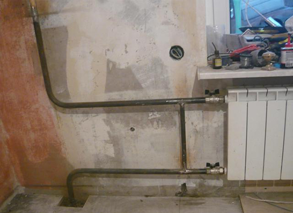
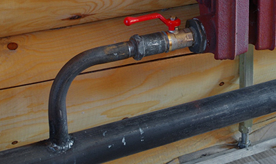
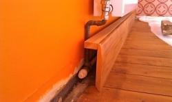
Photo 2. Connection of steel heating systems made using electric welding. Radiator connection type - lateral.
Electric welding two pipes in a rotary joint perform in the following order:
- Prepare your workspace and protective equipment.
- Remove chamfers from mating areas, dull the edges, remove burrs.
- Clean the internal weld.
- Clean the welding area 10 mm from the edge.
- Set the current value: for UONI 13/55 - 50-55 A; for CU-5 - 45 A.
- Weld the workpieces around the perimeter at three points. The gap between the parts is - 2 mm.
- Clean the "tack" areas and cut grooves in them with a grinder for welding seam.
- Perform a weld with electrode lift-off (pointwise).
- Place adjacent seams as close to each other as possible. (with overlap).
- Beat off the slag with a special hammer.
- Check the quality of the weld.
Welding defects:
- pores;
- loose fit of individual seam “scales”;
- unwelded areas;
- slag between the "scales".


Threaded connections
To cut threads, a ratchet die and thread-cutting dies are used.
Ratchet die makes the process easier, as it has guides for the tool to enter and a massive handle. Thread after die cutting - conical, often of poor quality (in inexpensive tools).
To obtain a cylindrical shape (which is present in threaded fittings), after the die it is necessary to perform second finishing pass with a die with a pipe thread.
Attention! For a second pass, use a domestic die holder with a guide, which is fixed at the required distance from the edge of the pipe. In the process of cutting the thread with a die The die holder is screwed onto the guide.
To seal threaded connections use flax with paste, anaerobic sealants.
Copper structures
Types of connections:
- Welding.
- Thread.
- Press fittings using a special crimping tool.
- High-temperature and low-temperature soldering. The strength of both types is the same, but after high-temperature soldering the pipe becomes unsightly (blackens).
Welding
Welding of copper pipes with a diameter more than 108 mm, and wall thickness over 1.5 mm performed by a qualified specialist. If you do not have experience, it is not recommended to connect pipes yourself.
Types of welding:
- tungsten-intergas;
- metal-intergas;
- acetylene-oxygen.
Depending on the type of welding, the appropriate filler material is selected.
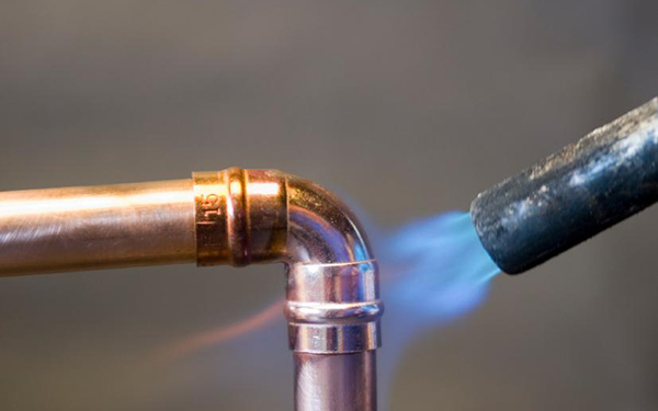
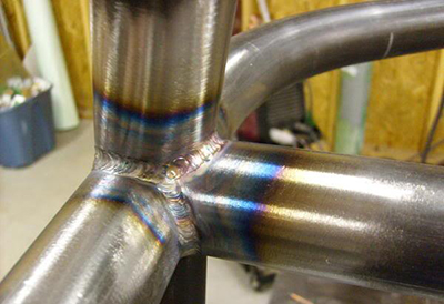
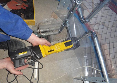
Photo 3. Welding copper heating pipes with filler material. Must be performed by a qualified specialist.
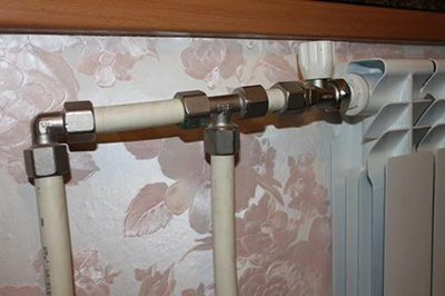
Thread
The connection is made using threaded fittings. They include brass compression ring, which, when tightening the connection, compresses the pipe with a tight fit. With further tightening, the end of the pipe is pressed against the groove on the fitting.
Technology of installation of rigid copper pipe into threaded fitting:
- Calibrate the end of the pipe with a special tool.
- Put a threaded nut and compression ring on it.
- Insert the pipe into the fitting.
- Press and tighten the nut first by hand, then with a wrench.
- Check the locking after each turn of the wrench. (immobility) of the pipe in the axial direction.
- Upon reaching immobility tighten the nut the last 2/3 of a turn, to slightly deform the end of the pipe, ensuring tightness.
Metal-plastic and plastic systems
Installation technology:
- calibrate the end of the pipe;
- put a compression sleeve on it;
- install the pipe into the fitting until it stops;
- put a compression sleeve on it;
- check the correctness of the installation through the hole in the fitting (the surface of the pipe should be visible throughout the hole);
- compress the sleeve with a special press.
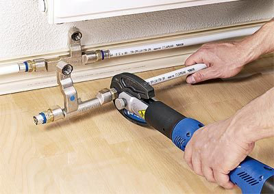
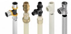
Fitting
Installation of metal-plastic and plastic pipes in heating systems is carried out using press fittings. Compression fittings with a split ring are not installed due to their low reliability (require periodic tightening).
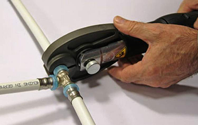
To crimp press fittings, you need crimping tool.
Advantages:
- Possibility of quality control of the crimp joint using a special hole on the fitting.
- The connection does not require maintenance.
- Ensuring tightness and resistance to loads.
Flaws:
- high cost of press fittings;
- Expensive professional crimping tool with attachments.
Polypropylene
For heating, polypropylene pipes with aluminum or fiberglass reinforcement are used.
Installation technology:
- Warm up the soldering iron before work 10 minutes to a temperature of 260±10 ºC.
- Cut off the workpiece with a special knife.
- Treat its end with a special cleaning agent to completely remove the aluminum layer.
- Degrease the joints with alcohol.
- Mark the distance, to which the workpiece will enter the welding nozzle: for size 16 – 13 mm; for 20 – 14 mm; for 25 – 15 mm.
- Insert the pipe blank and fitting into the soldering iron nozzles.
- Count the heating time: for sizes 16 and 20 – 5 sec; for 25 – 7 sec.
- Remove the parts from the soldering iron.
- Quickly, without allowing it to cool down, insert the pipe into the fitting. Fix the connection motionless: for sizes 16 and 20 – no less than 6 sec; for 25 – no less than 10 sec.
Attention! A common installation defect is overheating of material in the soldering iron, as a result of which the pipe flow in the fitting narrows.
Cross-linked polyethylene
The connections of cross-linked polyethylene blanks are made in two ways:
- press fittings;
- fittings with a sliding sleeve.
Installation with press fittings:
- The end face of the workpiece is calibrated.
- It is installed into the fitting nipple.
- A sleeve is crimped around the workpiece using a special crimping tool.
Cross-linked polyethylene is deformed when crimped and, due to its elasticity, fills all the irregularities and grooves of the fitting, ensuring the tightness of the connection.
To increase reliability, the press fitting design includes: 2 rubber rings:
- The first one is located under the uncompressed part of the outer sleeve. and acts as a compensator during mechanical displacement of the fitting.
- The second is located in the compressed zone. and acts as a compensator for the thermal expansion of the fitting.
Installation with fittings with a sliding sleeve:
- a plastic sliding sleeve is placed on the workpiece;
- the end of the part is expanded using a special extractor;
- the pipe is installed on the fitting nipple;
- The inserted sleeve is moved towards the fitting using a special tool.
The reliability of press fittings is higher than that of products with a compression sleeve:
- When the end of a PEX-b pipe is expanded by an extractor, microcracks occur, reducing the service life of the connection.
- The strength of the steel crimping sleeve is higher, than a plastic sliding one.
- The quality of the crimping can be visually controlled using a special hole in the press fitting. The sliding sleeve does not have this capability.
Laying heating pipes in the floor
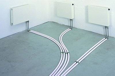
Methods of laying in the floor:
- inside the screed;
- in the space between the joists (when installing a wooden floor).
Requirements:
- Laying is carried out after installation of radiators and before the screed is completed.
- If the floor is wooden, the actions are carried out after installing the joists.
- All types of pipes are laid, except steel ones (due to possible corrosion).
Technology:
- Make a drawing of the system layout on the floor.
- Calculate the amount of material, necessary for laying solid sections (without joints).
- Place the blanks in the sleeve and secure to the base of the floor (when tightening). When fastening, take into account the thermal expansion of the material.
- If the floor is on joists, place the blanks in the sleeve in the holes between them, closer to their base.
- Perform the installation of connections between the beginning and end of the workpiece sections, which should be located outside the floor.
- Pressurize the system.
- Lay a screed or wooden floor.
Useful video
Video instructions for beginners on choosing pipes for a heating system.
Check seven times
Quality execution of pipeline layout tested by pressure testing, that is, by pumping excess pressure into the system. When using polymeric materials, it is recommended to perform 3 crimping cycles with operating temperatureto check the reliability of the connections and assess the effect of thermal expansion.

Comments