Step-by-step instructions for creating a solid fuel long-burning boiler with your own hands using drawings
Solid fuel boilers with long burning time help maintain heat without frequently adding firewood.
Instead of the usual 2-4 hours, one bookmark in long-burning boilers it is enough for at least 8-12 hours operation of the equipment. The exact time between loading depends on the design and type of fuel used.
Content
Drawings of solid fuel boilers of long burning
Long-term operation of the device with a heat exchanger on one batch of firewood ensures a special design:
- increased fuel chamber capacity - accommodates 2 times larger volume bookmarks;
- non-standard direction of ignition – the wood burns vertically downwards.
The fire covers the upper layer of fuel. Due to the metered supply of air flow, an even, weak flame is formed. The lower volume of the bookmark gradually heats up as the wood burns out.
Classical
In standard drawings they are established cylindrical heat generator. The rectangular body is not suitable for classic long-burning boilers.
The equipment works as follows:
- combustion chamber fill with firewood and light it from above;
- during the combustion process of fuel through a telescopic pipe on it a load with a hole for air circulation is lowered;
- oxygen enters the firebox through the chimney under the influence of natural draft or a fan;
- there is no heat exchanger in the classic scheme, the water for heating is heated directly.
In addition to firewood, peat or coke is used for kindling.
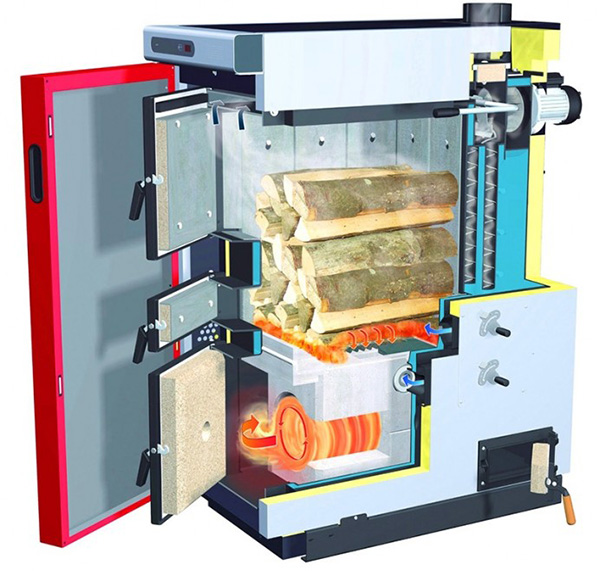
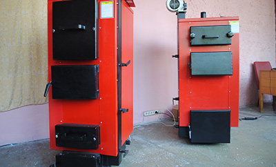
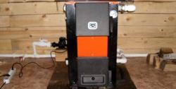
Photo 1. Classic solid fuel boiler with long burning time with firewood in the firebox and no heat exchanger.
Pyrolysis
In gas generator devices the wood smolders more slowly. Combustible smoke is released, which enters a separate zone and generates additional thermal energy. The design includes:
- Loading chamber. The process of pyrolysis combustion of fuel takes place in it.
- Afterburning section. This is where the gas burns.
- Heat exchanger. They are made in the form of a "shirt". Inside the heat exchanger, water is heated for subsequent release into the network.
- Air supply device. Provides the supply of primary (to the furnace) and secondary (to the afterburning chamber) flow.
- Throttle valve. To regulate the speed and volume of oxygen at the stage of the first ignition of the fuel.
- Devices for controlling the temperature and power of equipment.
Two cameras separates the fireproof cover from the nozzle and holes. The secondary air flow determines the rate of heating of the water inside the heat exchanger.
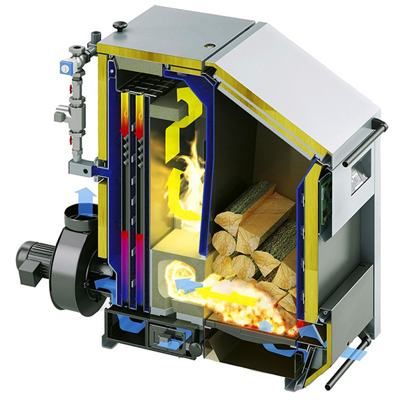
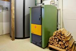
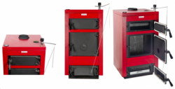
Photo 2. Pyrolysis boiler equipped with a loading chamber, heat exchanger, chambers separated by a fire-resistant ceiling.
Mine
Devices that work according to the principle of conventional fuel combustion, simpler than pyrolysis. The design includes:
- Firebox. This zone occupies from 50% of the volume equipment and is often rectangular in shape. Its height is slightly less than the length of the entire structure.
- Fuel loading hatch. It is installed above or to the side of the firebox.
- Ash pan. A chamber where ash and remaining coals naturally fall. It is installed under the firebox.
- Grate. It functions as a dividing grate between the internal sections of the boiler.
- Door. The dimensions are selected taking into account the possibility of simultaneous access to both the ash and the lower part of the firebox. To regulate the air volume, a damper is installed on the door.
- Section with heat exchanger. In projects of shaft boilers, water or fire-tube type designs are used. In the heat exchanger chamber, an opening is made for the entry of carbon monoxide gases.
- Chimney pipe made of metal or brick with a damper.
After loading and ignition, the fuel releases combustible gases. They enter the chamber with the heat exchanger through the hole, heating the latter. The smoke gives off energy and goes out through the pipe, and hot water enters the heating network.
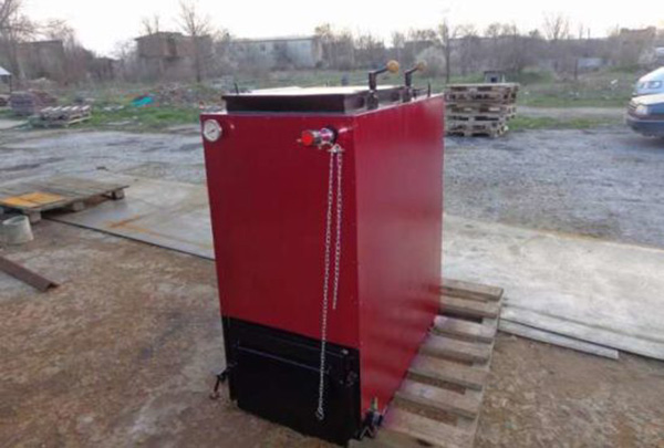
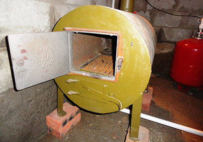
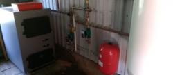
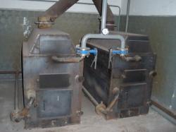
Photo 3. A long-burning shaft-type boiler with a heat exchanger in which the fuel releases combustible gases after ignition.
Step-by-step instructions for making a boiler from brick and metal
To choose the right design, it is recommended to consider the area of the room and the type of fuel. If the boiler is built for a garage or a small country house, there is no need for a water circuitHeating occurs from the surface of the device due to convection of hot air.
Attention! To increase efficiency and effectiveness, the device is supplemented forced air blowing system with a fanIf the room has a heating network with a liquid coolant, projects with a circuit in the form of a “coil” based on pipes are selected.
The type of fuel affects the chamber volume. For wood burning boilers suitable projects with increased firebox dimensionsWhen using pellets or shavings, it is possible to install a container for automatic feeding of granules.
It is easier to build a structure based on metal with brick. For this purpose, a heat exchanger is made from round and rectangular section profile pipes, which is installed directly into a brick boiler.

Necessary materials and tools
To make the body we use:
- Sand for mortar.
- Fireproof stove brick. As an alternative, a refractory analogue is used.
- Cast iron grate.
- Ready-made doors for ash pan and firebox (loading hatch).
The heat exchanger design includes:
- round pipe sections – 8 pcs. 800x50 mm, 4 pcs. 300x40 mm;
- rectangular pipe profiles – 5 pcs. 300x50 mm, 1 pc. 500x50 mm;
- pipe sections for the water inlet and outlet circuits in the system – 2 pcs. 100–150x50 mm;
- metal plates 60x40 mm to close joints.
To reduce costs, seamless products are chosen from alloy steel grade 20.
When constructing a heat exchanger and boiler, the following are used:
- grinder;
- cutter – gas or plasma version;
- pliers;
- forceps;
- drill;
- roulette;
- metal corners;
- welding machine;
- protective mask;
- level.
Suitable for assembling a long-burning heating device electrodes MP-3S or ANO-21.
How to build a structure with your own hands step by step
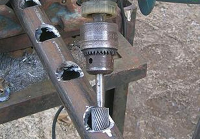
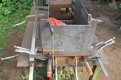
Heat exchanger is assembled by hand from 4 pipes 60x40 mm, round blanks D40 and D50 mm. Optimal wall thickness – 3-5 mm. From rectangular pipes of length 300 mm make vertical racks – by 2 in front and behind the register. To do this:
- On the back side of the two pipes for the front vertical posts cut out 4 round holes with a diameter of 50 mm. Uneven surfaces are sanded with a grinder.
- On each of the two rear upright tubes make 4 round holes with a diameter of 50 mm along the wide plane and 40 mm along the narrow side.
Important! Unevenness on the surface of the pipes is mandatory are being removed grinder for precision welding.
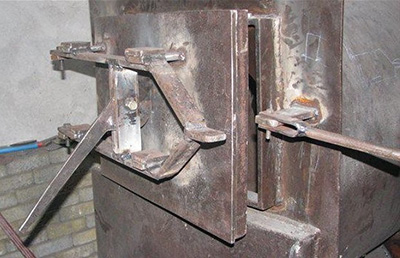
Preparing the rack for connection
To prepare the racks for connection, perform the following steps:
- In the lower rectangular pipe of length 500 mm, placed in front of the boiler, cut a round hole with a diameter of 50 mm to supply cold water.
- In the upper opposite corner of the rear vertical pillar cut a round hole of the same diameter to allow heated water to enter the heating system.
The front vertical pillars connect with rear 8 long (800x50 mm) round pipes. They are placed perpendicular to each other and welded. Between the rear pillars, a 4 short (300x40 mm) round pipes. They are installed below the front pillars. long (500x50 mm) rectangular pipe with a hole for return.
Important! All the edges are located strictly perpendicular to each other. Welding is performed on a flat surface to avoid distortions. It is better to connect the posts and pipes with an assistant.
When the heat exchanger frame is ready, short sections (100–150x50 mm) are welded to the connection points to the heating network, and all open ends of the racks are covered with pieces of metal.
To check heat exchanger for impermeability Before installation, the lower hole is closed and the container is filled with water through the upper one.
The structure is located in a vertical positionIf there are no leaks, the heat exchanger is ready for installation.
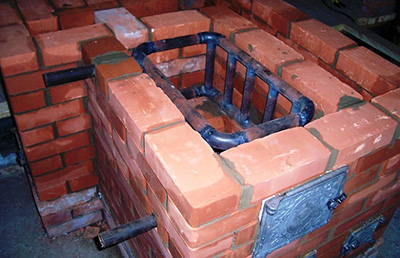
Before the construction of a brick building, they build concrete foundation taking into account the dimensions of the device. The blower chamber is laid out on it, the grate is mounted. The heat exchanger is installed with an inclination towards the cold water inlet.
The outlet pipe must be located above any upper point of the structure. The minimum difference in height is from 10 mm or more. This eliminates the risk of air lock formation and improves water circulation.
Attention! A gap must be left between the brick surface and the outer part of the heat exchanger. minimum 10 mm.
The finished structure with the pipe is lined with fire-resistant or fireclay bricks. The optimal thickness of the firebox walls is ½ block.
Openings are left in advance and installed 2 doors:
- lower – for access to the ignition point, cleaning the firebox and ash pan;
- top – for loading fuel.
The latter is installed on the lid or front wall of the device. The lower door can be replaced with two separate smaller ones if desired.
The masonry is in progress with mandatory dressing of sutures. The outer brick casing is erected at least above the pipes. by 20–30 mm. The upper part is covered with a cast iron sheet for quick dismantling if necessary. The design uses a chimney made of metal or brick remains. It is installed at a height from 5 meters or more relative to the grate level.
Connecting the device to the heating circuit
The finished device is designed to operate in an autonomous network. with natural and forced circulation of the energy carrier. In the first case, the following actions are performed:
- A straight pipe is drawn from the boiler, on which the security group is mounted.
- Using a tee equip a bypass.
- Device connected to the heating system through 2 pipes.
All joints must be wrapped with tow and covered sealant.
How to avoid problems during construction and operation
The equipment is installed only on a concrete base. The rolled steel cannot withstand the weight and the boiler sags. This leads to loss of tightness of the connections and damage to the pipes.
It is not recommended to use a homemade door for the firebox and ash pan. The slightest irregularities reduce the efficiency of burning wood.
Besides, coal fallout is possible through cracks with subsequent ignition. When making the door yourself, make it strictly for the opening, provide flaps and thermal insulation between the layers.
If a boiler with a heat exchanger is used in a local heating network, the circulation pump is installed on the return line. So the device works in a gentle mode throughout 6 years or moreTo solve the problem of low-temperature corrosion, a three-way thermostatic valve is installed on the bypass (jumper) and adjusted by 55 degrees.
A persistent creosote smell and smoke in the boiler room indicate low fuel quality. Cheap wooden sleepers are not suitable for heating and form ash and coal residues on the walls in less than a day of burning. To eliminate heat loss through the chimney, the latter is equipped damperIt prevents the escape of heated air and reduces the rate of fuel combustion.
Useful video
The video shows one of the schemes for creating a solid fuel boiler with minimal costs.
Pre-launch Check Method
Basic welding skills are enough to build a long-burning boiler with a heat exchanger without outside help.
Detailed instructions help to assemble a device with a heat exchanger for heating a house area up to 100 m2 with six 7-section cast iron radiators and 2-pipe wiring.
In accordance with SNiP, before the first start-up of the boiler, perform 24-hour hydraulic test. To do this:
- shut-off valves and taps are opened;
- water is introduced into the system;
- the pressure is increased to 1.3 atm.
A simple method helps to ensure that there are no leaks. Be sure to check the threaded connection areas and welds. The pressure level should remain unchanged. If any problems are detected, the boiler is disconnected from the heating network and the problems are eliminated.
Comments