The ideal temperature in the house is his merit! Connecting the heating manifold: what is it and how to do it
Collector distributes liquid from the main line to several circuits. It mixes flows from parallel branches and has recently been increasingly used instead of the usual types of wiring.
Content
Collector heating device
It is widely used in construction ray diagram heating. Here, separate pipelines are laid to each radiator. This allows you to regulate the air temperature in each heat exchanger.
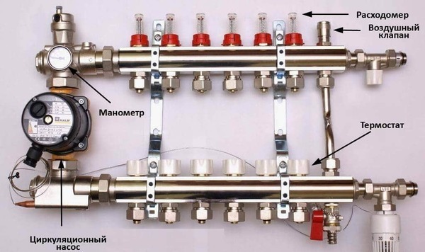
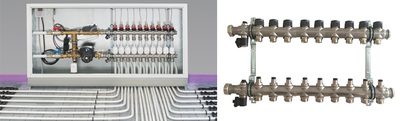
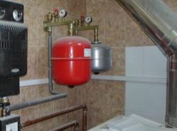
Photo 1. Collector for heating systems. The arrows show the components of the device.
It is in the beam system that the collector is used. It has the following characteristics:
- Provides automatic air removal from the heating system.
- Disables a single radiator.
- Disables a group of radiators when necessary.
- Distributes heated coolant to radiators and underfloor heating pipes.
- Returns cooled coolant to the heating boiler pipes.
The beam system also uses at least 2 combs, the totality of which is called a collector. One the comb answers for heated coolant, second — for cooled.
Reference. Not only the collector, but also the heating devices can be switched off separate taps, which are located directly on the radiator.
The combs are installed on the body flow meter or thermostat and other elements.
How to choose a place for installation?
In multi-storey buildings, collector groups must be installed on all floors, this simplifies checking the serviceability of devices and adjusting their operation.
The groups are mounted in special niches located at a small height from the floor.
In the niche too combs and fittings are placed.
In the absence of niches, collector groups are placed in any rooms with the required humidity. Suitable for such purposes are corridor, closet, pantry.
The equipment is covered with special cabinets, overhead or built-in. Holes for pipes are made in their side walls.
Calculation of the system
Formula for calculating collector heating looks like this:
S0 = S1 + S2 + S3 + Sn.
In this formula S1-Sn — the cross-sectional area of the outgoing branches, where n — branch number. S0 — cross-sectional area of the comb.
Before applying the formula They determine the number of heating circuits, make a drawing and only then carry out calculations.
After use The final version of the diagram is compiled using the formula, taking into account additional devices and indicating each individual group of pipelines.
How to calculate the correct pipe diameter?
To create an effective heating manifold, it is not enough to just build a diagram. You also need to determine correct pipe diameter.
When choosing pipes, consider:
- Hydraulic lossesIf pipes of different diameters are used in the system, this will inevitably lead to hydraulic losses.
- Speed of movement of the coolant. The water must not cool down before it reaches the last radiator.
- Volume of coolant. Large diameter pipes reduce fluid loss, but at the same time this increases the cost of heating the coolant.
It is also important to carry out the calculations correctly, this is will help increase efficiency the entire heating system.
The formula for calculation is as follows:
m = P x V
When calculating the optimal pipe diameter It is recommended to use special programs. They will make the result more accurate.
Installation process, system connection
Process installation of the manifold block consists of several stages:
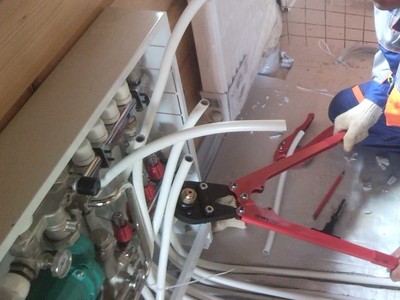
- They are installing the elements of the collector block.
- Determined by the orientation of the inlet pipe. It will depend on what type of boiler for the heating system was chosen.
- Fix the branch pipe on a metal bracket using clamps.
- They check whether they interfere with the free passage of pipelines return and feed elements.
- The pipes are attached to the sideIt is important to note that their orientation depends on which side will be more convenient for mounting all other equipment.
The quality of the assembly is checked using the maximum temperature and maximum power of the pump. The test passes at least 3 hours. If no leaks are detected in the system during this time, it is considered to be operational.

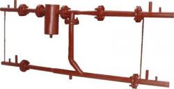
How to connect a single-pipe manifold, diagram
To connect a single-pipe manifold, a pipe with a diameter of not less than 76 mm or radiators. Radiators should be connected to a pipe if possible. 2 ways.
Attention! The prerequisite for this type of connection is the presence of an attic space. It is also important to consider the possibility of connecting a pump to increase the speed of the coolant.
When compiling connection diagrams The following factors are taken into account:
- arrangement of system elements;
- pipe junction;
- connection to the boiler;
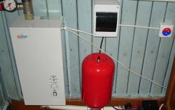
- expansion tank location;
- location of radiators, fittings, pumps and drain cocks.
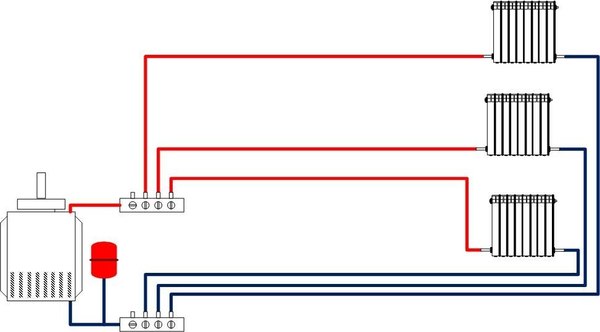
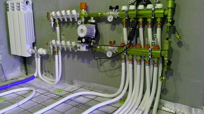
Photo 2. Diagram of connecting the collector to a single-pipe heating system. The device is installed after the boiler.
Radiators must be additionally equipped with taps in order to, if necessary, shut off the water supply not in the entire system, but in a specific section of it.
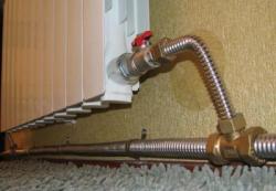
Adjusting the device
The heating manifold has a built-in flow meter, which controls water consumption.
The flow meter is installed on the return branches collector. It blocks or partially blocks the flow of energy carrier at the moment when the set temperature is reached.
In some cases, the system additionally equipped with a temperature sensorIf it is not there, the flow meter is adjusted manually.
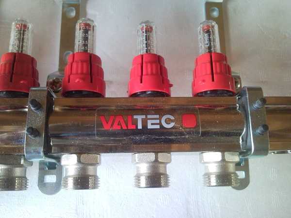
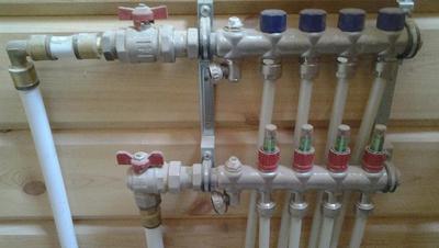
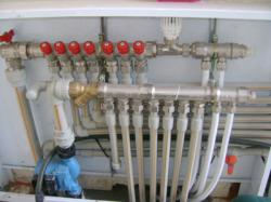
Photo 3. Flow meter on the heating manifold. The device monitors water consumption, thereby regulating the temperature in the system.
Setting up without a flow meter, how to adjust the temperature through the device
Setting up collector heating without a flow meter laser thermometer. In this case, it will help to regulate the temperature valve overlap.
It is important to write down, how many turns were closed valves to regulate the system later.
Useful video
Watch the video, which explains how to properly connect the circulation pump to the heating manifold.
Pros and cons of the design
When installing collector heating additional devices need attention. They will help to simplify the operation of the entire system.
The positive side is the radial mounting scheme, in which each heat exchanger can be adjusted separately.
This also helps to increase heat transfer.
The downside is that for collector heating a separate room will definitely be needed or at least a niche, which may not always be convenient.

Comments