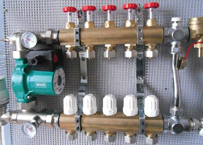
Normalizes the temperature in each part of the room - heating distribution manifold
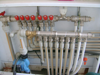
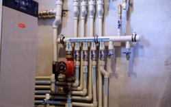
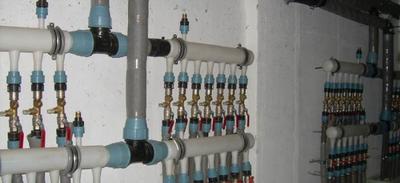
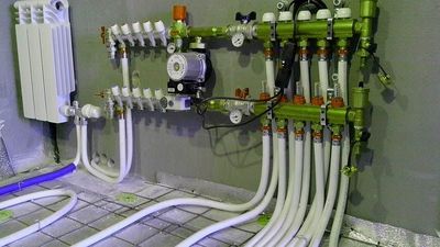
Distribution manifold or comb for heating - a device with multiple terminals to which all branches of the system are connected.
This device monitors the state of pressure, temperature and other indicators at each section of the system.
The simplest device looks like this on a regular pipe with a round or square cross-section, several branches for branches and connections for inclusion in the heating main. More sophisticated models are additionally equipped with sensors, thermostats, mechanical and electronic valves and other devices for automatic control.
Content
- What is a heating distribution manifold for?
- Types
- What sizes are there?
- How to choose a distribution manifold for heating systems
- How many contours are there on the body?
- Pressure and flow rate thresholds
- The process of installing a comb with your own hands
- Cabinet under the comb
- Is it possible to make a structure from polypropylene?
- DIY installation
- How to regulate
- Useful video
- Manufacturers
What is a heating distribution manifold for?
These are two connected blocks, each with its own function:
- Control of hot coolant supply to each branch: if necessary, any branch is closed using valves and shut-off valves.
- Pressure adjustment in each branch, due to which an even temperature is achieved in all rooms.
In private houses with a large area and several floors, collectors are installed on each of them - this is allows you to regulate the temperature in each room.
The system with a collector has advantages:
- heating is stabilizing regardless of the number of contours and their length;
- uniform load on pipelines and radiators;
- correct return of cooled coolant;
- even temperature in all rooms;
- coolant cleaning from foreign particles;
- easy adjustment of the system operation (when installing thermostats, flow meters and mixing units);
- installation of collector allows you to easily exclude any branch from the outline to carry out repair and maintenance work, carry out an emergency shutdown of any part of the system.
Design
Two combs (one supplies, the other takes away), valves. The following are added to this base according to the configuration:
- three-way valves;
- hydraulic arrow;
- brackets;
- flow meters;
- other additional mechanical and electronic automation.
The design varies according to the projected capacity and degree of automation, but the basic details are: comb and shut-off valves.
Operating principle, adjustment
The manifold ensures the separation of the coolant flows along the branches connected to it. When installing the manifold, heating control is carried out separately for each branch. The standard number of connected branches: 2-12.
The system can be easily expanded by adding new branches. The indicators are monitored for each circuit in accordance with the parameters of the premises.
In essence, the manifold is a unit of the system in which the supply and return combs are responsible for the supply and removal of the coolant. Installed pipes connect individual circuits to the central highway.
Reference. Comb sizes depend on the number of planned contours, but when designing the system, the possibility of expansion should be taken into account. The collector can always be improved and expanded by adding additional branches.
This is taken into account when choosing the location of the collector. It should be convenient access and enough free space for expansion.
Types
Collectors are made from materials resistant to adverse environments:
- steel;
- copper;
- brass;
- polymer compositions.
The devices also differ in the number of branches they are designed for. The maximum number of additional branches is 12.
Classified by the complexity of the system being installed. Devices with a simplified design are not designed for the installation of complex additional devices. For advanced automated systems, combs with built-in sensors, electronic control devices and reinforced fittings are produced. The following are installed:
- pressure sensors And temperatures;
- thermostats;
- Automatic control units coolant supply;
- electronic valves with fine adjustment of response (for temperature regulation, liquid drainage, etc.);
- air ducts;
- mixers.
What sizes are there?
It is important to understand, what exact cross-section size is needed for a specific system, especially when made by hand.
Diameter is the main value for selecting and calculating a collectorAccording to the rules, the cross-section of the collector is equal to or greater than the sum of the cross-sectional areas of all connected branches.
This applies to both distributors, the inlet and outlet.
Calculating the length of the collector, you need to rely on the distance between the pipes: they are separated from each other by a distance equal to three collector diameters.
Ready-made distributors are produced with the same proportions.
How to choose a distribution manifold for heating systems
When purchasing a distributor, it is important to focus on the following points:
Material (for feed and return):
- Brass: The combs are cast, which ensures durability and long service life. High cost.
- Stainless steel: welded product, very durable, but when in contact with an aggressive environment it gradually loses its properties.
- Plastic (polypropylene): They are not inferior to metal ones in terms of characteristics, but they are inexpensive.
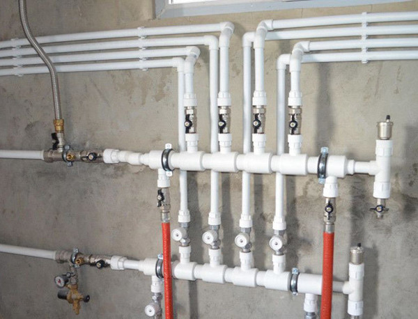
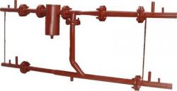
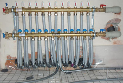
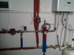
Photo 1. Heating distribution manifold made of polypropylene. The design contains eight units.
How many contours are there on the body?
Ideally the number of contours corresponds to the taps on the comb. However, it is advisable to buy with the calculation of possible expansion of the heating network. Plugs are installed on the bends that are not in demand at the moment.
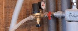
Pressure and flow rate thresholds
Before purchasing any equipment calculations are made for the heating network, which give an idea of the pressure and flow of the coolant in the system. The collector is selected according to technical characteristics so that a small safety margin remains - the system may have pressure surges and excess of the calculated liquid flow.
The process of installing a comb with your own hands
Most of the instruments and devices of the collector are subject to corrosion, therefore It is installed in a dry place. Since the main function of the unit is to distribute the flow of hot coolant, it is logical to place it closer to the boiler.
Important! Around the installation site repair work should be carried out in advance, so that later the connections and devices do not end up stained with paint and plaster.
Cabinet under the comb
Next, a cabinet is installed in which the unit is located. The main function is keep the distributor closedIf a built-in unit is planned, then a space for the cabinet is cut out in the wall.
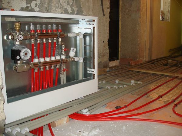
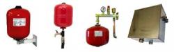
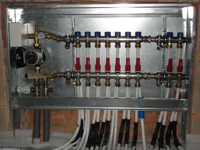
Photo 2. The heating manifold cabinet for underfloor heating. It hides all the heating equipment from view.
Purchasing a manifold cabinet will significantly simplify the installation and maintenance of the unit.
All pipes and switches are closed from prying eyes., where the circulation pumps are also located. The cabinet itself is compact, which allows it to be mounted on a wall or built in.
- External cabinets have noticeable dimensions, usually 1x2 meters, but the size may vary depending on the number of pumps and other additions.
- Built-in - located in the wall, only the door is visible from the outside. This is combined with hidden wiring and pipes laid under the floor covering. Overall, it has an aesthetic appearance.
Installation of pumps will require electrical wiring of appropriate power., usually a separate cable. Electrical wiring is designed in advance taking into account the presence of electronic devices.
The optimal location for the unit is a room that will not be damaged in the event of a pipe break or leak. A living space or storage room will not do.. The unit will be used for a long time, so the appearance of liquid cannot be avoided at least due to the wear of the valves. A separate room will allow you to detect problems faster.
The dimensions of the cabinet can be calculated based on the average dimensions of the equipment: from 0.5 to 1.5 meters - this is determined during the system design process. Stages:
- At first the comb is installed and pipes are connected.
- The cabinet is installed in the selected location. For a built-in wardrobe, a hole is prepared in the wall in advance.
- The unit is assembled according to the diagram., additional devices are installed: valves, taps, faucets, etc.
- The collector is turned on and checked.
Is it possible to make a structure from polypropylene?
Collector design easy to reproduce with your own handsFor a private house with a small area, a polypropylene comb is suitable.
For this purpose, the following are purchased:
- pipes;
- tees;
- pipes;
- shut-off valves;
- additional devices depending on the work plan and project.
Polypropylene pipes convenient for easy soldering And the ability to replace any section of pipe.
You can also buy a ready-made version with one-way bends, polypropylene or stainless steel.
Attention! When designing, it is important to consider that This is one of the main units of the heating system. It is better to immediately make or buy a manifold with a larger number of branches than originally planned. This will help to avoid a complete replacement of the unit in the future.
DIY installation
Installation rules:
- the comb is fixed to the wall, at medium height or near the floor;
- It is desirable that the collector be located above the heating main - in this case it is easier to remove air through it;
- a cabinet is being installed (on the wall or in a prepared hole in the wall);
- in it in advance make holes for the pipeline;
- the length of the branches is approximately equal;
- to the distributor connect devices and valves;
- configure the system.
How to regulate
The adjustment consists of in defining and setting the required parameters temperature and flow rate of the coolant.
The temperature is set by turning the thermostatic head., as for consumption, the process is not simple. There are no established rules for regulating this indicator, especially since the parameter is set for each circuit separately.
The smart way is to do a hydraulic calculation using special software (it can be found on the website of the collector manufacturers). However, if you do not want to delve into it, you can try to do it empirically - if the rooms are cool, the consumption increases, if it is hot - it decreases.
Reference. Gradually, a certain regulation algorithm will be developed, but not immediately - due to the inertia of the system.
Useful video
Watch the video to learn how to make your own heating distribution manifold.
Manufacturers
Guaranteed excellent quality of the collector is offered by: Soletrol, Rehau, Oventrop, Meibes, GREENoneTEC.
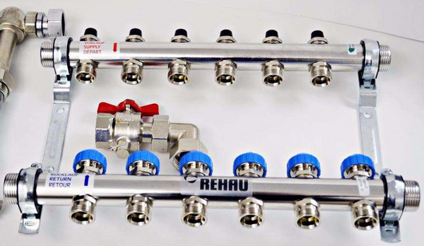
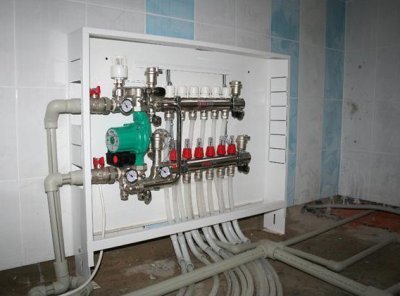
Photo 3. Heating distribution manifold from the manufacturer Rehau. The product is made of stainless steel.
From budget options - Stout. These products are manufactured in Italy, under strict quality control on modern equipment. In addition, they are best suited to Russian conditions.