Secrets of technology: different schemes for connecting a warm water floor to a heating system
Before directly connecting the heated floor, it is important pay attention to many parameters.
For example, the area of the room, its heating method, the height of the ceilings, the number of walls and certain designated areas of the room in a private house.
Content
Features of connecting underfloor heating to central heating
This type of additional heating of the room has positive and negative sides.
Pros:
- full distribution of heated air masses by height in rooms with high ceilings;
- uniform heating of the surface rooms in all its zones;
- air circulation and no drafts reduce the amount of dust formation;
- the possibility of developing allergies is excluded and respiratory diseases in the owners of the house;
- the ability to regulate electricity consumption;
- is an independent system for heating rooms.
Cons:
- price of installation works the efficiency of such a heating system is quite high;
- the possibility of installation in high-rise buildings is excluded with a single-pipe type of central heating system;
- the formation of a cement screed and insulation increases the floor level to 15 cm.
Possible problems
When putting into operation the heating of the premises in the form of warm floors, certain problems may arise difficult situations.
Uneven heating of the surface
Trouble may be lurking in movement of the coolant through the circuits.
Since they have different lengths, the speed of liquid supply to pass through long sections of the circuits will require a longer period of time. Therefore, in such circuits the water cools down faster.
Pipeline damage
A leak in a pipe or a sharp drop in pressure in it leads to to a breakthrough in the underfloor heating system. This results in a decrease in the amount of coolant and, as a consequence, the destruction of the floor.
If the heating level is low and a leak appears, a thorough inspection of the surface using a thermal imager is required.
It is necessary to check each contour of the heated floorIf damage to a section of the pipe is detected, it is replaced with a new one.
The reason for incomplete heating can be determined by checking each underfloor heating circuit separately.
Electrical equipment defect
If there is no leak, the floor may not heat up due to malfunction of the circulation pump and thermostat, operating from the mains.
Using a multimeter or indicator screwdriver, check for the presence of voltage in them.
You also need to pay attention to checking the temperature sensors on the thermostat.
Connection diagrams
Exists several ways commissioning of a room heating system of this type.
In each of the schemes, it is necessary to provide for the absence of particles in the pipes, otherwise this will lead to clogging of the elements of the underfloor heating structure.
Through a separate input
With this method Dry operation of the circulation pump is not permitted. For this purpose, a relay is installed that regulates the pressure or flow rate.
It is also permissible to use surface-mounted thermostat, which allows blocking the operation of the pump when it crosses the lower temperature threshold.
The most effective option is installing the regulator, which adjusts the room heating temperature in accordance with the outside temperature of the room.
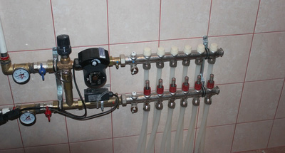
Through vertical wiring
The main goal of such a scheme is the process of restoring the existing radiator system.
By fixing the underfloor heating pipes directly to the riser, you can double the amount of heat received. This is explained by the fact that at the same temperature value in the supply pipe and return pipe, at the moment of the difference in the pipes of the heated floor it will be higher than in the radiator.
If present in residential premises 4 risers coolant of the two, it's in transit, and from the rest, warm water from the central heating system is used.
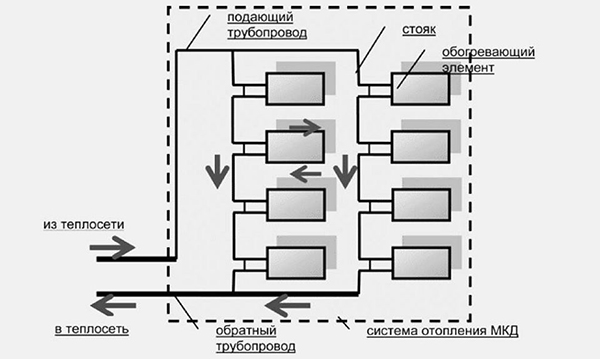
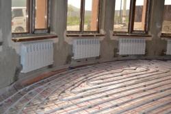
Photo 1. Diagram of connecting a water-heated floor to a heating system using vertical wiring.
The sequence of actions according to this scheme:
- installation of new exchangers heat in place of previously used radiators;
- parallel fixation of the secondary circuit from the heated floor.
Important! When carrying out the process, it is necessary PVC pipe applications the same length.

One-pipe system
This is the scheme does not provide for flow regulation coolant and lowering its temperature.
The water heated floor is connected to the central heating system using a riser. This can be done by replacing the radiator with a heated floor circuit.
The difference in thermal loads between the central heating system and the underfloor heating system should not be more than 5-10 degrees.
In this case, room temperature can be controlled using a circulation pump and a thermostat.
In the absence of coolant in the riser, the pump operates automatically terminates.
To maintain a comfortable temperature in winter, you can use the used scheme peak electric boilerThis element will be able to perform this function with the help of a thermostat, provided that it is connected to the central heating on one side and to the heated floor on the other.
How to connect to individual heating
Connection diagrams for individual heating are available four types: single-pipe, double-pipe, gravity, combined.
Single pipe
Its other name is "Leningradka". It is one of the simplest and does not require large financial investments.
To implement this scheme, one main line for hot water is needed, and the circuit increases its overall length. The whole process is carried out thanks to circulation pump.
It is being installed in the center of the highway. The water floor heating circuit is installed after the pump, and the return lines are installed before it.
The open sections of the pipe are fixed regulators for management and mixer for floor heating.
Attention! The length of the loop used in this circuit should not be above 20–30 m.
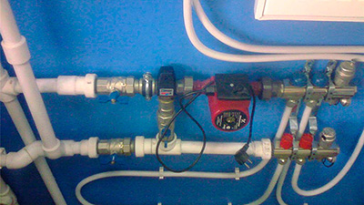
Double pipe
It is considered the most effective for the full functioning of heated floors.
Unlike the previous one, this scheme implies presence of individual pipes, connected to the boiler - for supplying hot water and return.
Thanks to the use of ball valves and mixers In an open area, it becomes possible to put into operation an underfloor heating system.
The circuit used in this circuit should not be more than 50 m.
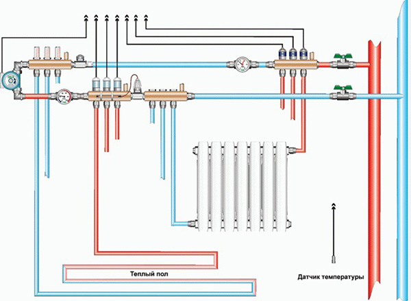
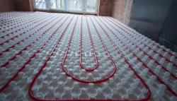
Photo 2. Two-pipe connection diagram for underfloor heating using ball valves and circulation pumps.
Gravitational
Through the pipeline water circulates naturally. The circuit connection to this floor heating system is made in accordance with the main slope. The connection is made at the beginning of the room, and the return line is at the end.
The main pipe parameter must start from 3.2 cm.
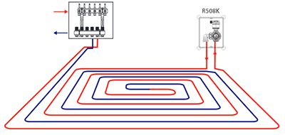
The pipeline can be in the form of snakes or spirals.
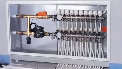
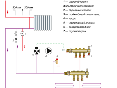
Combined: water floor and radiators
This system is distinguished by two properties: circulating and hermetically sealed.
Both components of the circuit are fixed to a common riser. The coolant goes to the floor circuit through the mixing unit. There, to maintain a comfortable floor temperature, cold water can be added to it from the return line.
After this, the coolant is divided into separate branches. using collector combs. Warm floors are supplied with their own circulation pump.
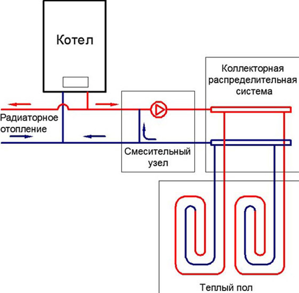
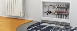
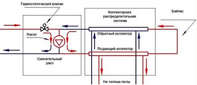
Photo 3. Combined connection diagram for underfloor heating: with a boiler, batteries, manifold system, mixing unit.
Nuances combined scheme:
- mandatory organization presence in the underfloor heating system and radiators independent temperature regimes;
- necessity of use large quantities additional components of the process;
- control of the combined system implies the presence of mixing units with thermostatic valves, weather-dependent regulation by an external controller, room sensors, etc.
To the boiler
Schemes are found collector, serial, parallel, with two-way and three-way valve.
Collector
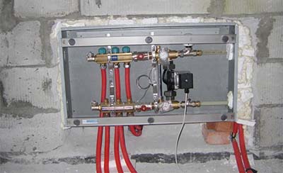
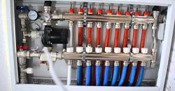
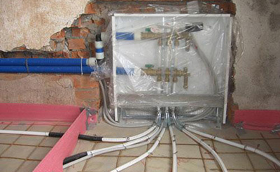
The point is that it is produced manifold group connection (drain valve, circulation pump, air vent, mixer and shut-off valves located on the pipes) and pipes, and the collectors themselves are fixed with boiler tubes.
The process of installing the collector cabinet and forming the floor is underway.
Sometimes Thermo-valves are installed instead of conventional shut-off valves. They indicate the throughput capacity due to the use of a thermal cylinder with paraffin.
As in the combined circuit, in the collector circuit the following is produced: mixing cold water if necessary. A mixer pump is fixed between the manifold and the supply line. His third outing allows liquids to pass through in front of the recoil tube.
The support sleeve, clamping ring and nut enable connection to pipe manifolds.
Fitting required to fix the manifold, pipe and valve.
With two-way valve
This component of the system is thermal head with liquid sensor. This valve is also called a feed tap, because it allows water to be added only when it is open.
This scheme provides mandatory installation of a bypass with a safety valve. It is necessary for situations with excessive pressure: when this indicator increases, part of the liquid is discharged into the return line.
Reference! This scheme is applicable for a room area not exceeding 200 sq. m.
With three-way mixing valve
This method is considered optimal. The main components are: thermal heads and a separate temperature sensor. The circulation pump provides the movement of the coolant. The three-way valve adds the required amount of liquid to the supply pipe. Its installation is carried out on the collector branch of the output on the return line.
Without using a circulation pump, the length of pipes in the circuits should not exceed 40 m. If it is available, there are no length restrictions.
Parallel and serial
The first one involves installation bypass instead of a bypass valveThis is required for the coolant to pass through it.
That is, when the contours work the liquid will not flow without stopping, and otherwise, a bypass valve is used to unload the pump. Such a valve is installed manually.
The temperature of the outgoing liquid must match its inlet temperature.
A series circuit differs from a parallel circuit not only in the method of connection, but also in the fact that the output flow goes into the boiler, and the temperature matches the temperature of the water-heated floor.
Useful video
A video showing a boiler piping diagram for connecting a heated floor with mandatory installation of a mixing unit.
DIY installation
If you take into account all the features of the various schemes and carefully study the instructions, it is possible connect yourself heated floors without turning to professionals.